CNC machining prototypes are essential for verifying your design before mass production. The fastest way to get high-quality CNC prototypes is to follow three core steps: optimize your CAD file for machining, choose the right material and tolerances, and select a machining partner with clear quality control. This guide walks you through each step with real-world examples, helping you avoid common mistakes and achieve accurate prototypes on time.
01What Are CNC Machining Prototypes?
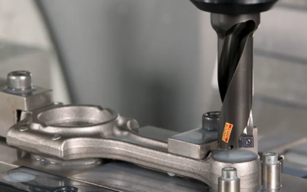
CNC machining prototypes are functional parts produced using computer-controlled cutting tools—mills, lathes, or routers—directly from digital 3D models. Unlike 3D-printed prototypes, CNC prototypes offer production-grade material properties and surface finishes, making them ideal for mechanical testing, fit checks, and pilot runs.
Why choose CNC for prototypes?
Uses the same materials as final production (aluminum, steel, plastics, etc.)
Achieves tight tolerances (±0.005″ or better)
Provides repeatable, dimensionally accurate parts
No tooling costs, suitable for 1–200 units
02Step 1: Prepare Your CAD File for Machinability
The most common cause of delayed prototypes is a design that cannot be machined efficiently. Follow these rules:
Avoid sharp internal corners – Use radiused corners (minimum 1/32″ or 0.8mm for end mills).
Limit deep cavities – Depth-to-width ratio should not exceed 4:1 for standard tools.
Add draft angles – Not mandatory for 3-axis milling, but 1–2° helps on vertical walls.
Check wall thickness – Minimum 0.020″ (0.5mm) for metals, 0.040″ (1mm) for plastics.
Include proper hole callouts – Specify through or blind, diameter, and depth.
Real-world case: A medical device startup sent a CAD model with 0.010″ wall thickness in 6061 aluminum. The machinist rejected the file, causing a 3-day delay. After revising to 0.040″ walls and adding fillets, the prototype was completed in 48 hours.
03Step 2: Select Material and Tolerances Based on Function
Match your material to the prototype’s purpose—not just the final product.
Do not over-specify tolerances. Tighter than ±0.001″ adds 30–50% cost and lead time. Only apply critical dimensions where mating parts require it.
04Step 3: Choose the Right Machining Partner
For prototypes, look for shops that specialize in rapid CNC prototyping, not high-volume production. Key criteria:
Online quoting with DFM feedback – Upload STEP/IGS files and receive manufacturability analysis within 24 hours.
Material in stock – Avoid shops that need to order raw stock (adds 5–7 days).
Inspection report included – Full CMM or caliper check with pass/fail data.
Lead time options – Standard 5–7 days, expedited 2–3 days, rush 24 hours (premium cost).
Common mistake: Choosing a production shop that runs 500+ part batches. They often push prototypes to the back of the queue. Instead, use a dedicated prototype house or a service with a separate rapid prototyping division.
05Step 4: Request a Clear Setup Sheet and Inspection Plan
Before machining starts, ask for:
Tool list and step-over amounts
Fixturing method (vise, soft jaws, or custom fixture)
Critical dimension checklist with target values
Surface finish expectation (as-machined, bead blast,anodize)
This prevents miscommunication. One automotive supplier failed to specify thread depth on a prototype housing. The shop tapped only 0.3″ deep instead of 0.6″, making the part unusable. After adding thread callouts to the drawing, the next prototype passed first time.
06Step 5: Inspect and Validate the Prototype
When you receive the parts:
1. Visual check – Look for tool marks, burrs, or missing features.
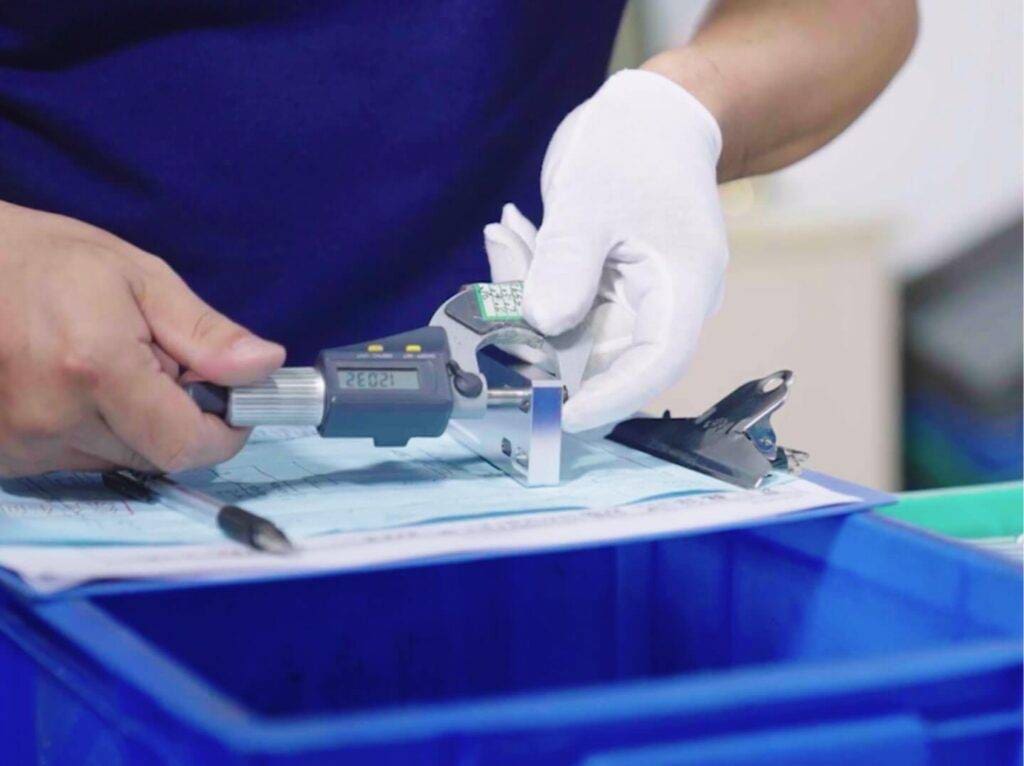
2. Dimensional check – Measure critical tolerances with calipers or micrometers.
3. Functional test – Assemble with mating parts under expected loads.
4. Material verification – If possible, check hardness or conductivity.
If any dimension is out of spec, request a corrective action report from the machinist. Reputable shops will re-run the part at no charge for their error.
07Common Challenges and How to Overcome Them
Challenge 1: Long lead times
Solution: Use local machine shops with in-house CNC capacity. For remote suppliers, pay for air shipping and expedite fees only for the first article—then order multiple copies at standard speed.
Challenge 2: High cost for one-off parts
Solution: Combine multiple prototypes into a single fixture plate. For example, machine three different bracket designs from one block, then cut them apart. This saves setup time and material.
Challenge 3: Surface finish too rough
Solution: Specify a finish requirement in your PO. “As-machined” leaves visible tool marks. Request “bead blasted” or “light sanded” for a uniform matte finish without extra cost.
Challenge 4: Material warping after machining
Solution: Stress-relieve the material before final cutting. For aluminum plate, specify “stress-relieved” when ordering. For plastics like Acetal, use annealed stock.
08Best Practices from Industry Standards
ISO 2768-mK – Default tolerance for general dimensions (medium class). Use this unless tighter is needed.
ASME Y14.5-2018 – For GD&T callouts on critical features.
Surface finish Ra 3.2 µm – Standard as-machined finish for most prototypes.
Minimum corner radius = cutter diameter + 10%. Use 1/8″ (3.175mm) end mill for 0.063″ radius.
These standards are recognized globally. Including them in your drawing makes the quote more accurate and reduces back-and-forth.
09Actionable Next Steps
To get your CNC machining prototypes right the first time:
1. Audit your CAD model against the six design rules in Step 1.
2. Create a simple drawing listing 3–5 critical dimensions and tolerances.
3. Get quotes from three prototype shops – compare lead time, material availability, and inspection policy.
4. Order a first article (one piece) before committing to multiple copies.
5. Inspect within 24 hours of delivery and report any issues immediately.
Remember: The goal of a prototype is to learn and improve. Even a failed prototype provides valuable data—as long as you document why it failed. Apply those lessons to your next iteration.
By following this guide, you will reduce CNC prototype lead times by 30–50% and avoid 80% of common machining errors. Start with a clean CAD file, pick the right material, and choose a partner who gives you DFM feedback and inspection data. That is the fastest path to reliable CNC machining prototypes.


