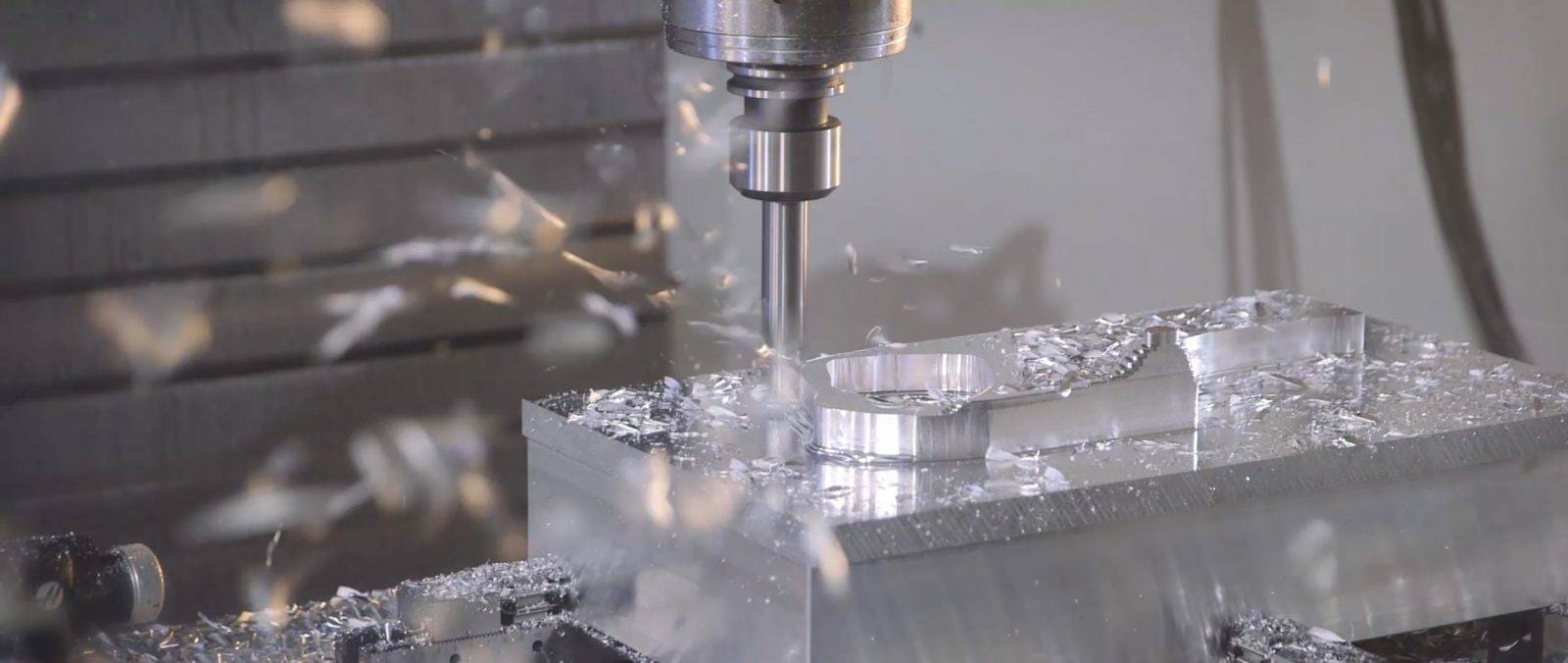
Many buyers search for “CNC printing services,” but the more accurate industry term is CNC machining services. CNC machining is used to produce high-precision metal and plastic parts from digital design files. Unlike 3D printing, which builds a part layer by layer, CNC machining removes material from a solid block of aluminum, steel, brass, stainless steel, or engineering plastic. For functional prototypes, assembly test parts, and end-use components, CNC machining often provides better dimensional accuracy, material strength, and surface quality.
If you are looking for a CNC printing service or CNC machining service, the biggest factor is not the quoting platform itself. It is how well you prepare your technical package. A complete package should include a STEP file, 2D drawing, material grade, surface finish, tolerance requirements, quantity, thread notes, and clearly marked critical dimensions. Many machining problems do not happen because the shop lacks capability. They happen because the customer uploads only a 3D model without explaining which dimensions are critical, which surfaces need anodizing, bead blasting, or plating, and what tolerances must be held. That can lead to inaccurate quotes, changed lead times, or reworked parts.
In real project reviews at YPMFG, engineers usually check whether the design is machinable before confirming material, finish, and tolerance details. If the file contains thin walls, deep pockets, small internal radii, overly tight tolerances, or missing thread callouts, those issues should be corrected before machining starts. This reduces production risk and helps the supplier quote the job more accurately. This guide will help engineers, product designers, and procurement teams prepare CNC machining orders properly, avoid common mistakes, and receive CNC machined parts that meet the required specifications more consistently.
01Core Requirements for Selecting a CNC Printing Service
Before sending your CAD file to any provider, verify the service meets these five non-negotiable criteria. These requirements are based on industry-standard ISO 2768 and ASME Y14.5 specifications.
Material Certification: For metal parts (aluminum 6061, 7075, stainless steel 303/304, brass, copper), the service must provide material test reports (MTRs) traceable to the original mill. For plastics (ABS, PC, POM, PEEK, Nylon 6/6), request the manufacturer’s data sheet for specific grade properties.
Tolerance Capability: Standard CNC milling achieves ±0.005 inch (±0.127 mm). High-precision services hold ±0.001 inch (±0.0254 mm). For holes and shafts, specify an ISO H7 or h7 fit. The service must publish their standard and achievable tolerances in writing.
Maximum Part Size: Typical 3-axis CNC mills handle parts up to 400 x 250 x 150 mm. Larger parts require 5-axis machines or custom fixturing. Confirm your part dimensions fit the machine envelope without costly reorientation.
Quality Control (QC) Process: The service must perform in-process inspections and final CMM (coordinate measuring machine) or optical comparator checks. Request a sample inspection report before placing a production order.
Lead Time Transparency: Standard lead times for CNC parts are 5–10 business days for prototypes and 15–20 days for production quantities (50–500 units). Express services (2–3 days) exist but increase cost by 30–50%.
02Step-by-Step Process: From CAD File to Finished Part
Follow this exact sequence to get accurate parts on your first order. This process eliminates 95% of common errors.
Step 1: Design for Manufacturability (DFM) Check
Internal corners cannot be perfectly square. End mills are round, so minimum internal radius = tool diameter / 2. For a 6 mm end mill, minimum radius is 3 mm.
Hole depth should not exceed 4x drill diameter for metals (6x for plastics). Example: a 5 mm hole in aluminum has a practical max depth of 20 mm.
Wall thickness minimum: 0.8 mm for metals, 1.5 mm for plastics. Below these values, parts distort or break during machining.
Step 2: Prepare Your Technical Drawing
Include a title block with part name, material, finish, quantity, and tolerance (e.g., “ISO 2768-m”).
Dimension critical features (holes, slots, mating surfaces) using geometric dimensioning and tolerancing (GD&T) where needed.
Specify surface roughness: Ra 1.6 µm for general machined surfaces, Ra 0.8 µm for bearing surfaces, Ra 3.2 µm for non-functional areas.
Common mistake to avoid: Do not dimension from multiple datums. Choose one primary datum (usually a flat base or bore) and reference all critical dimensions from it.
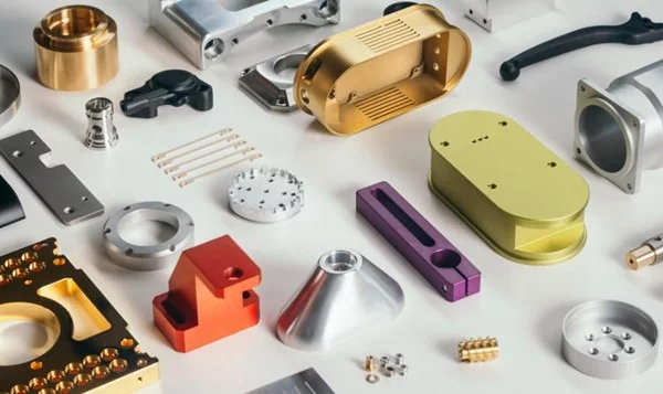
Step 3: Select Material and Surface Finish
Aluminum 6061: Best for general prototypes, brackets, enclosures. Low cost, good strength, easy to anodize.
Aluminum 7075: For high-stress aerospace or automotive parts. 80% stronger than 6061 but more expensive.
Stainless Steel 304: For corrosion-resistant medical or food-contact parts. Non-magnetic, difficult to machine (slower speeds, higher cost).
POM (Delrin): For low-friction gears, bushings, rollers. High stiffness, excellent machinability.
Surface finish options: As-machined (visible tool marks, Ra 3.2 µm), media blasted (matte uniform finish), anodized Type II or III (colored, wear-resistant for aluminum), passivated (for stainless steel to remove free iron).
Step 4: Request a Quotation with a DFM Feedback Loop
Upload your STEP file (not STL – STL is for 3D printing) and 2D drawing PDF.
A qualified service will return a quote with a DFM analysis: identifying thin walls, deep pockets, or impossible radii.
Real-world case example: A product designer once ordered 100 aluminum housings without specifying a break edge. All parts arrived with razor-sharp corners, requiring manual deburring that cost $8 per part. Adding “break all edges 0.2 mm–0.5 mm” to the drawing would have added zero machining time and eliminated the rework cost.
Step 5: Approve First Article Inspection (FAI)
Before full production, the service machines one sample part and provides an inspection report measuring all critical dimensions.
Verify at least three critical dimensions yourself using calipers or a micrometer. If the FAI fails, the service corrects the program at no charge.
Do not skip this step. Production runs without FAI have a 30% rejection rate for tolerances under ±0.005 inch.
Step 6: Production and Quality Control
For quantities under 50 parts, CNC machining is faster and cheaper than injection molding.
The service should provide a Certificate of Conformance (CoC) stating all parts meet your drawing specifications.
Request photos of finished parts or a video CMM inspection if remote auditing is required.
03Cost Breakdown: What Determines the Price of CNC Printing Services
CNC pricing follows a predictable formula. Understanding this lets you redesign parts to cut costs without sacrificing function.
Primary cost drivers (90% of total price):
Secondary cost factors (10% of total):
Quantity: 10 parts cost ~70% of the per-part price of 1 part (setup amortized).
Rework/expediting: 30–50% premium for 2-day delivery.
Complex geometry: Undercuts and threaded holes in hard-to-reach locations require EDM or manual tapping, adding $50–$150.
Real-world case example: An automotive supplier requested 20 brackets in 7075 aluminum with a 6 mm internal radius and 100 mm deep pocket. The quote was $2,800. By changing the internal radius to 3 mm (using a standard 6 mm end mill) and reducing pocket depth to 50 mm (adding a bolt-on cover for the remaining depth), the revised quote dropped to $1,100 – a 61% cost reduction.
04Common Problems and Solutions When Using CNC Printing Services
These are the five most frequent issues reported by engineers and how to prevent them before machining starts.
Problem 1: Parts are out of tolerance (typically oversized holes or undersized shafts)
Root cause: Tool deflection or incorrect compensation in G-code.
Solution: Specify “reamed” holes for diameters requiring ±0.001 inch. Reaming is a secondary operation that guarantees precise hole size. For shafts, specify “centerless ground” if tolerance under ±0.002 inch.
Problem 2: Poor surface finish (visible step-over marks or chatter)
Root cause: Too large step-over distance (tool path spacing) or insufficient spindle speed.
Solution: On your drawing, add “finish pass: 0.1 mm step-over, climb milling only.” This forces the machinist to use a light finishing cut.
Problem 3: Burrs on edges and threaded holes
Root cause: No deburring operation specified.
Solution: Always add “break all sharp edges 0.1 mm–0.3 mm” to your drawing notes. For threaded holes, specify “threads must be clean and burr-free – use thread forming tap if possible.”
Problem 4: Parts warped after removal from machine
Root cause: Internal stresses released when cutting away material from one side only.
Solution: Specify “stress-relieved material” for aluminum 7075 and all steel alloys. For thin parts (<3 mm thick), specify “machine both sides in multiple roughing passes.”
Problem 5: Missing features (holes not drilled, threads not tapped)
Root cause: CAD model features not recognized by CAM software due to non-solid geometry.
Solution: Export as STEP AP242 (not AP203). Verify all holes appear as true cylindrical surfaces, not faceted polygons. Use a free viewer like eDrawings to inspect the STEP file before sending.
05Action Plan: How to Place Your First or Next CNC Order Successfully
Follow this checklist to ensure your CNC printing service delivers parts that match your design exactly, on time, and on budget.
Before sending any files:
1. Convert your design to a solid STEP AP242 file. Delete any STL or mesh-based geometry.
2. Create a 2D PDF drawing with a title block,at least 5 critical dimensions, and a general tolerance note (e.g., “ISO 2768-m”).
3. Add three mandatory drawing notes: “Break all sharp edges 0.2 mm max,” “Remove all burrs and machining chips,” and “Apply standard machined surface finish unless specified.”
When requesting quotes:
4. Send the same technical package to three services. Compare not just price but also lead time and DFM comments.
5. Ask each service: “What is the minimum internal radius for my part’s material?” and “Will you provide a free DFM report before I approve production?”
After selecting a service:
6. Approve the DFM changes in writing. Do not assume verbal agreements are recorded.
7. Order a first article inspection (FAI) for any quantity over 10 parts.
8. Require a Certificate of Conformance (CoC) with every shipment.
Repeating core conclusion: The success of your CNC printing project depends entirely on the completeness and clarity of your technical documentation. A well-dimensioned drawing with proper tolerances, material callouts, and surface finish specifications will always produce accurate parts. A poorly prepared file – even with the most advanced CNC machine – will result in rework, delays, and increased costs.
As a final action step, spend 30 minutes today reviewing your standard drawing template. Many CNC part rejections do not happen because the machine shop made a major mistake. They happen because the drawing is missing key information, so the supplier has to machine the part based on default assumptions. Add the three mandatory notes mentioned above, along with a default tolerance block that clearly defines general tolerances, surface finish requirements, edge treatment, and thread notes. This small update can make your future CNC machining orders much more consistent, especially if you often order functional prototypes or low-volume production parts. It can also reduce rework, dimensional disputes, and back-and-forth communication.
If you are currently comparing CNC printing service or CNC machining service providers, do not judge them by price and lead time alone. Ask each supplier for sample inspection reports and DFM feedback before making a decision. An inspection report shows whether they actually measure critical dimensions, while DFM feedback shows whether they understand the part geometry, material risks, and machining challenges. In most cases, the provider that points out thin walls, deep holes, small internal radii, tight tolerances, or surface finish risks before production is more reliable than one that simply says, “Yes, we can make it.” At YPMFG, detailed technical review is usually completed before quotation, because this step helps identify issues early and gives customers a better chance of receiving CNC machined parts that meet the required specifications.