
01Best CNC CAD Programs: Top Picks Guide
What You Need to Know Right Now
If you are searching for a CNC CAD program, your main goal is to find software that can help you design parts and generate accurate toolpaths for your CNC machine. A practical CNC CAD program should be able to convert your design model into machine-readable G-code for cutting, milling, carving, or multi-axis machining. When choosing the right program, you should not focus only on a long feature list. Instead, match the software’s capabilities to your actual machining needs, such as 2D sheet cutting, 3D surface carving, or complex multi-axis precision milling. For engineers, product designers, and manufacturing companies, the right CNC CAD program can improve programming efficiency, reduce machining errors, and shorten the process from design to finished part. As a brand focused on high-precision custom manufacturing services, YPMFG understands from real CNC machining projects how important the connection is between CAD design, CAM programming, and G-code output. This guide provides a direct, clear, and actionable method to evaluate and choose a CNC CAD program based on real-world machining scenarios, without unnecessary software brand names, vague claims, or marketing fluff.
1. Core Capabilities Every CNC CAD Program Must Have
Before comparing options, verify that any program you consider includes these essential features:
2D Drawing & Editing – Create precise geometry (lines, arcs, circles) with dimensioning.
3D Modeling – Solid or surface modeling for complex parts.
Toolpath Generation – Convert geometry into cutting paths (profile, pocket, drill, etc.).
Post‑Processor – Output G‑code compatible with your machine’s controller.
Simulation – Visualize the cutting process to detect collisions or errors.
Why this matters: A program missing any of these will force you to use multiple tools, increasing errors and setup time.
2. Real‑World Scenarios: Which Program Fits Your Work?
Scenario A – 2D Cutting (Plasma, Laser, Router for flat parts)
Common case: A small workshop needs to cut 100 identical brackets from 6mm steel sheet.
What you need: Fast 2D CAD with nesting, lead‑in/out, and kerf compensation.
Key decision points:
Does it import DXF/DWG reliably?
Can it automatically arrange parts to save material?
Does the post‑processor support your plasma/laser controller?
Action: Prioritize programs that offer “2D CAD + CAM” in one interface. Avoid full 3D suites – they slow you down.
Scenario B – 3D Carving (Wood, Foam, Wax for molds)
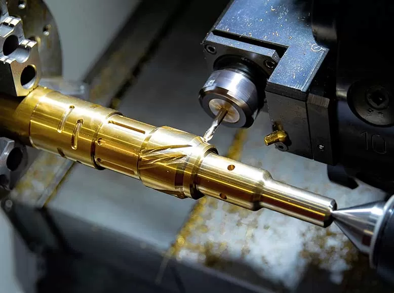
Common case: A furniture maker creates a decorative 3D relief on a chair back.
What you need: 3D modeling with sculpting or relief tools, plus raster or 3D toolpath strategies.
Key decision points:
Can it import STL/OBJ files from design software?
Does it support ball nose end mills with stepover control?
Is there a roughing + finishing toolpath workflow?
Action: Look for programs that specialize in “artistic CAD/CAM” – they handle large 3D meshes efficiently.
Scenario C – Multi‑Axis Milling (Prototypes, Metal Parts)
Common case: An engineering shop machines a turbine blade requiring 4‑axis simultaneous cutting.
What you need: Full 3D solid modeling, 4/5‑axis toolpaths, and advanced collision avoidance.
Key decision points:
Does it support indexed or simultaneous multi‑axis?
Can it simulate the entire machine kinematics?
Is the post‑processor customizable for your rotary table?
Action: Invest in a program that offers a dedicated multi‑axis module. Entry‑level 2.5D software will not work.
3. Step‑by‑Step Selection Process (Follow This Order)
Step 1 – Define your machine and materials
Machine type: router, mill, lathe, plasma, laser
Controller: Mach3, LinuxCNC, GRBL, Fanuc, etc.
Materials: wood, aluminum, steel, foam, plastic
Step 2 – List your typical part complexity
2D profiles only → any 2D CAD/CAM works.
2.5D pockets and drilled holes → needs basic CAM with cycles.
True 3D surfaces → requires 3D toolpath strategies.
Multi‑axis → dedicated module necessary.
Step 3 – Test compatibility before committing
Download a free trial (most programs offer 15‑30 days).
Import one of your existing DXF/STEP files.
Generate toolpaths for a simple square pocket.
Run the simulation.
Output G‑code and compare with a known good file from your machine.
Step 4 – Verify post‑processor availability
Check if the program includes a post for your exact controller.
If not, ask if you can edit or request a custom post.
Without a correct post, the program is useless.
Step 5 – Evaluate learning resources
Official documentation, video tutorials, and user forums.
A program with poor learning support will cost you weeks of trial and error.
4. Common Mistakes That Waste Time and Money
Buying a program because it’s popular for 3D printing – CNC milling requires different toolpath logic.
Ignoring the post‑processor – Many users buy software, then discover their machine can’t run the G‑code.
Choosing a program with a steep learning curve for simple 2D work – You do not need a $10,000 multi‑axis suite to cut plywood circles.
Not testing with your own files – Demo examples always work perfectly. Your complex assembly may not.
5. Frequently Asked Questions (Direct Answers)
Q: Can I use free CAD programs for CNC?
A: Yes, many free CAD tools exist. However, free programs rarely include CAM (toolpath generation). You will need a separate CAM program. This two‑step workflow works but increases file transfer errors.
Q: What is the difference between CAD and CAM in CNC?
A: CAD (Computer‑Aided Design) creates the geometry. CAM (Computer‑Aided Manufacturing) creates the toolpaths. A “CNC CAD program” usually means integrated CAD/CAM – both functions in one.
Q: How do I know if a program supports my machine’s G‑code dialect?
A: Look for the post‑processor list. Common controllers (Mach3, GRBL, LinuxCNC, Fanuc) are supported by most programs. Unusual industrial controllers may need a custom post.
Q: Do I need 3D CAD for 2.5D work?
A: No. 2.5D (pockets, holes, profiles on flat material) only needs 2D geometry. True 3D surface machining requires 3D models.