In hydraulic cleaning, fuel injection, and precision spray systems, that humble brass nozzle withstands the impact of tens of megapascals. When "high pressure" and "precision" meet, CNC machining becomes the life and death line that determines the life and performance of the nozzle. Why do some nozzles in the same drawing develop deflected jets after three months of use, while others can operate stably for two years? The answer lies in the game between material properties, cutting parameters and cavity geometry.
01 From rough to finished product: a challenge strung together by a timeline
Brass has always been known to be easy to cut. However, high-pressure working conditions have completely changed the rules of the game. The timeline goes back to the stage when the material buyer purchases materials: Brass with a lead content of less than 2% is extremely prone to intergranular corrosion when high pressure is applied, and if the lead content is too high, it will weaken the strength of the thread. There is an industrial processing plant in South China that once used recycled brass at the same time, causing a batch of nozzles to burst directly during the 15MPa test. This was not a failure of the material itself, but the result of the contempt for the word "high pressure".
It is at the CNC programming stage that the real watershed lies. The design engineer set the contraction angle of the nozzle inner cavity to 14 degrees, but ignored the "cavitation effect" when the high-pressure fluid passes through the sharp edge. After three months, on-site feedback showed that the nozzle flow rate dropped by 22%. After dismantling, it can be seen that the junction between the shrinkage section and the straight hole is full of honeycomb corrosion pits. And this "stress concentration" phenomenon is exactly the most hidden trap in high-pressure processing.
The selection of the tool path is also based on time logic. Using a clockwise spiral cutter during rough machining can prevent chip clogging. However, if the same direction is continued during finishing, the ductility of brass will cause a 0.02mm burr to appear at the exit. For a nozzle hole with a diameter of 0.3mm, this size can change the jet shape from a cone to a twisted twist.
02 Spiraling Cognition: From Geometric Precision to Physical Performance
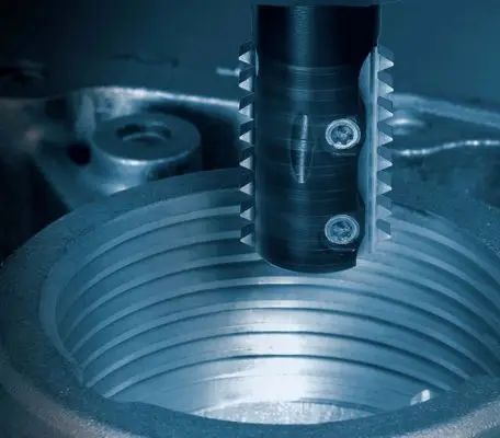
Traditional processing thinking focuses on dimensional tolerances, but the real challenge of high-pressure nozzles lies in "fluid dynamic integrity." One company was once proud of its ±0.005mm inner hole accuracy, but serious jet oscillation occurred under a working pressure of 40MPa. Why is this? Microscopes revealed spiral tool marks left by machining, microscopic grooves that serve as the source of eddy currents.
The analogy presented by the nozzle is exceptionally clear: high-pressure water flows through the nozzle like a symphony orchestra passing through a narrow doorway. Once the porch walls are rough, the musicians will bump into each other and all that will come out is noise. For the same reason, the roughness Ra value of the brass nozzle surface must be controlled below 0.4 μm, and the relevant direction of the knife marks should be consistent with the flow direction of the fluid. This requires specifically adopting the combined strategy of "up-milling + minimum quantity lubrication" in the CNC program, and adding a 30-second extrusion grinding step at the end. However, many factories sacrifice the overall performance of the entire nozzle just to save these 30 seconds.
To expand the field of view laterally, the processing standards of aero-engine fuel nozzles can be used as a reference. Although there are differences in materials, the common law has always been true in high-pressure scenarios, that is, any geometric mutation must be rounded, and the radius cannot be less than 0.1mm. This rule also applies to the step holes of brass nozzles. Unfortunately, most general CNC programming tutorials usually do not emphasize this point, and engineers can only learn from failure cases in reverse.
03 Reverse reasoning: working backwards from failure to process
The commonly seen thinking path is "determine the process → create the product → detect the failure". A more efficient way is to think in reverse: Assuming that the nozzle will inevitably fail unilaterally under high pressure conditions, then which weaknesses are most likely to become the main source of the problem?
Once the angle deviation of the sealing cone surface is more or less than ±0.5°, leakage will occur. During the pressure test operation, the bubbles will be as dense as stars.
Deburring of cross holes : Manual chamfering can easily cause eccentricity and cause jet deflection.
At the end of the thread : the stress concentration coefficient can reach 3 times, and fatigue cracks often start here.
One company spent three months investigating abnormal wear of the nozzle, and finally found out that the cause was that in the CNC program, the G41 tool radius compensation command was mistakenly set to left compensation. It is this one character difference that causes the diameter of the throat of the actual processed nozzle to be 0.015mm larger. When high-pressure fluid passes through, the speed decreases and the atomization effect weakens sharply. The solution is as follows. Forcibly add tool wear variable monitoring to the program, automatically pause every 50 pieces processed, and prompt to measure the throat aperture.
04 FAQ Q/A
Q1: When processing brass nozzles, should the coolant be oil-based or water-based?
First choose oil-based minimum quantity lubrication. Water-based coolant will accelerate dezincification corrosion of brass and form micro-cracks under high pressure. Oil-based lubrication can reduce the heat generated by friction, thereby preventing softening and deformation of the inner cavity.
Q2: What are the consequences if the burrs at the nozzle outlet are not cleanly removed?
A2: The jet is deflected and the flow rate decreases. The burrs cause the outlet boundary layer to change, causing the fluid to break away from the wall and eject in a filamentous form. At the same time, the effective cross-sectional area decreases by more than 15%.
Q3: How to judge whether the CNC processed nozzle is suitable for high pressure working conditions?
A3: Carry out a step-up pressure-holding test, starting from 5MPa, increasing step by step toward the working pressure, and each step must be maintained for 2 minutes. If the pressure drop exceeds 5%, or an audible hissing sound occurs, it is unqualified.
05 Repeat core ideas and action suggestions
Machining brass nozzles through high-pressure CNC is not as easy as simply "making a hole." This places demands on engineers to simultaneously master three different dimensions: material metallurgy, fluid mechanics and cutting dynamics. The key point has always been true: the geometric accuracy of the surface does not equate to functional reliability under high pressure; every second of processing time compression is likely to be at the expense of the life cycle.
Three action suggestions are put forward that can be implemented directly:
1. Immediately review the existing nozzle drawings and add at least R0.1mm rounded corners to all inner cavity right angles.
2. Forcibly add the "extrusion grinding" process at the end of the CNC program, even if it will increase the cost of each product by twenty seconds.
3. Build a database of failure situations. Every time the nozzle is dissected, take photos of the inner cavity and classify and archive them according to categories such as "cavitation-wear-fatigue".
The harshness of the high-pressure environment will not compromise the aesthetics of the materials. The jets of the brass nozzle are the final judgment on CNC machining decisions. Can your craftsmanship withstand the next round of pressure inspection?