The process of rotating workpieces under the control of a computer control system is called Turning CNC (CNC turning). It is suitable for precision manufacturing of rotary parts such as shafts and discs. Based on actual processing cases, this article systematically explains the core parameter selection of Turning CNC, provides solutions to common problems, and also puts forward optimization suggestions, which can help operators master key skills quickly.
01What is Turning CNC?
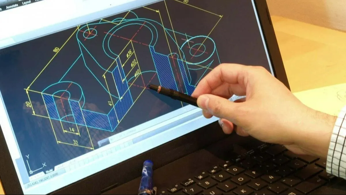
Turning CNC uses the CNC system to control the tool to travel axially or radially towards the workpiece to achieve the processing of outer circles, inner holes, end faces, threads and other features. Compared with ordinary lathes, Turning CNC has the advantages of high automation, good repeatable positioning accuracy, and one-time molding of complex contours.
An example is that a factory specializing in the manufacturing of automobile parts used Turning CNC during the processing of transmission shafts, and combined with constant linear speed control, it finally succeeded in keeping the diameter tolerance firmly within the range of 0.01mm, and improved production efficiency by 40%.
02Core parameter settings of Turning CNC
To ensure quality and efficiency, the basis is to correctly set the processing parameters. The following are three categories of parameters that must be confirmed first:
1. Three elements of cutting
The cutting speed, that is, Vc, should be selected based on the tool material. The tool materials include carbide, ceramics, CBN, etc., as well as the hardness of the workpiece. For example, when processing 45 steel and the hardness of 45 steel is HB200, for carbide tools, the recommended Vc range is 120 to 180m/min.
During lathe processing, there is a parameter called the feed amount, which is f. When rough turning, the feed amount should be 0.2 to 0.4 mm per revolution. When finishing the car, the feed rate should be 0.05 to 0.15 mm per revolution.
Depth of cut (ap) : rough turning 2-5mm, fine turning 0.1-0.5mm.
2. Coordinate system and tool setting
Use the trial cutting tool setting method or use the probe to automatically set the tool to ensure that the workpiece coordinate system coincides with the machine tool coordinate system.
The first piece of each batch must be verified for tool offset compensation.
3. Cooling and lubrication
Use water-based emulsion or oil-based cutting oil. The recommended pressure is 0.5 to 1.5MPa to ensure that the chips can be discharged smoothly.
Keywords related to processing parameter optimization are integrated into the prompts, which directly determine the surface finish of the part and the life of the tool. It is recommended to record the wear status of the tool every 2 hours and dynamically adjust the feed rate.
03Typical application scenarios of Turning CNC
According to common processing requirements, the following five specific types of parts are most suitable for Turning CNC.
1. High-precision shafts (motor shafts, turbine shafts)
2. Complex contour rotary body (ball head, thread, curved surface)
3. Non-ferrous metal disc sleeves (aluminum wheel hubs, hydraulic valve sleeves)
4. Slender shaft (length-to-diameter ratio >10 requires a tool holder)
5. Multiple varieties of small batch parts (quick mold change has obvious advantages)
Case study: There is a hydraulic parts factory that originally used ordinary lathes to process piston rods. The time required for a single workpiece was 12 minutes, and the pass rate was 92%. After switching to Turning CNC, through optimization of programming, the time required for a single workpiece became 7 minutes, and the pass rate increased to 99.5%.
04Frequently asked questions and solutions (Q/A format)
Q1: What should I do if vibration marks appear on the surface of Turning CNC machining?
A1: First, check the tool overhang, which should be less than or equal to 3 times the diameter of the tool holder. Also check the spindle bearing clearance. At the same time, there are two methods, one is to reduce the depth of cut, and the other is to increase the rotational speed to avoid the resonance zone.
Q2: How to solve the problem that the hole diameter is out of tolerance and tapered?
Thermal elongation in the Z-axis direction is compensated, or a special boring cycle is called, pausing for 0.5 seconds every 0.2mm depth to release cutting stress.
Q3: How to deal with chips entangled on the workpiece or tool?
Increase the feed rate to make the chips thicker and easier to break. At the same time, adjust the chip breaking groove to a "V" shape, or add a high-pressure coolant jet direction.
Q4: What should I do if the tool tip height is not correct after changing the tool?
Reuse the tool setter to calibrate the Z-direction zero point of each tool, and then add G41/G42 tool radius compensation to the program. This is the operation of A4:.
Q5: How to avoid deformation of thin-walled parts after clamping?
A5: Replace soft claws or fan-shaped claws to increase the contact area and distinguish rough turning from fine turning. Before finishing turning, release the clamping force to 60% of the original value.
05Maintenance and safety guidelines for Turning CNC
To ensure long-term stable operation, the following three systems must be implemented:
Daily inspection : coolant level, air pressure value, emergency stop button function.
Weekly maintenance : clean chip conveyor residue, lubricate guide rails, and check spindle drive belt tension.
To perform monthly calibration, an instrument called a laser interferometer is used to detect the pitch error, then generate a compensation table, and finally import this compensation table into the CNC system.
Regarding the safety red line, there are regulations that prohibit manual cleaning of chips when the spindle is rotating. When the first piece of the program is executed, it must be executed in a single segment and the override must be reduced to 10%.
06Restatement of core views and suggestions for action
Core point of view: The machining quality of Turning CNC depends on the balance between reasonable selection of parameters, tool path optimization, and cooling and chip breaking control. Any neglect of a single dimension will lead to a decrease in efficiency or accuracy.
Suggestions for action :
1. Quickly start building the "Turning CNC Process Parameters Benchmark Table", group them according to materials, and record the most suitable cutting speed and feed amount.
2. Before each batch is processed, a "three-step verification" must be performed. These three steps are: first, the tool data must be reviewed, then the direction of the cooling nozzle must be confirmed, and finally, the simulation graphics must be compared, that's it.
3. A chip breaking effect analysis meeting will be organized every month. According to the shape of the chips, that is, long rolls, flakes, and granular shapes, the feed parameters will be optimized.
In such a situation, tool path optimization can use the trochoidal turning strategy in CAM software to reduce sudden load. According to actual measurements, it can extend tool life by more than 30%, and it is recommended to update the post-processor template every quarter.
After using the above method, a machining workshop increased the mean time between failures of Turning CNC from 160 hours to 220 hours within three months, and the overall efficiency increased by 25%. Start executing the parameter check list right away from the next batch of parts, and you'll see quantifiable quality improvements.