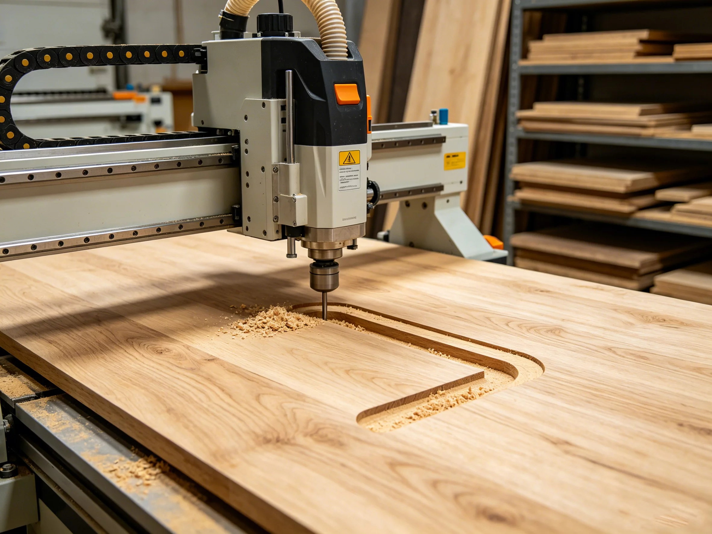
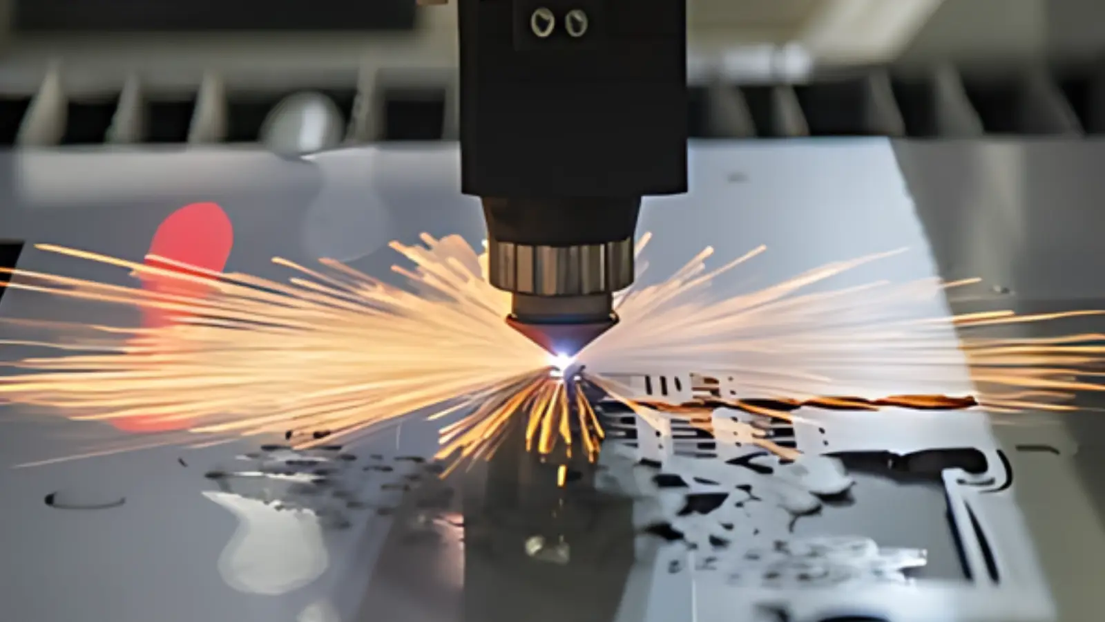
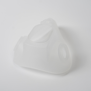
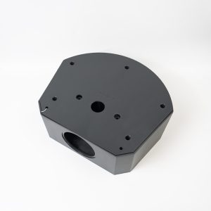
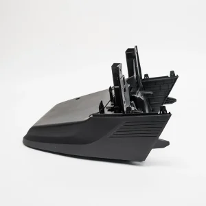
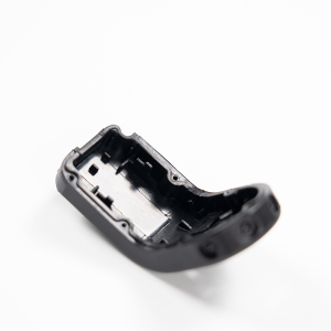
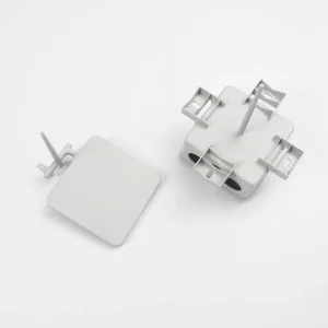
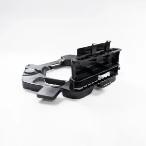
CNC milling foam is a fast and reliable way to produce lightweight prototypes, molds, display models, and architectural models. Compared with manual cutting, CNC foam milling gives better control over dimensions, curved surfaces, and edge details, especially when the same geometry needs to be repeated. To get clean and accurate foam parts on the first try, you need the right foam material, cutting tool, spindle speed, feed rate, and chip removal method. At YPMFG, foam prototype and model projects are usually reviewed based on part use and surface requirements before toolpaths and machining parameters are set, helping reduce burrs, tearing, and surface marks.
What you need to know before starting
Foam is not like metal or wood. It cuts easily but can also tear, melt, or produce dust that clogs your machine. Using the right end mill and spindle speed is the difference between a smooth surface and a ruined workpiece.
Case example: A common workshop situation
A small prototyping shop needed to mill a 3D contour in a block of polyurethane foam (density: 6 lb/ft³). First attempt used a standard two-flute end mill at 12,000 RPM and 30 IPM. Result: melted edges, fuzzy surfaces, and poor detail. After switching to a single-flute O-flute compression bit at 16,000 RPM, 80 IPM, and a 0.1” depth of cut, the same part came out clean, with no fuzz and sharp corners. This is the typical outcome when following foam‑specific best practices.
Essential tooling for foam
Single‑flute “O” flute end mills – Best for most foams (EPS, XPS, polyurethane, tooling foam). Large flute volume clears chips quickly.
Compression spirals – For double‑sided foam boards; cuts clean top and bottom edges.
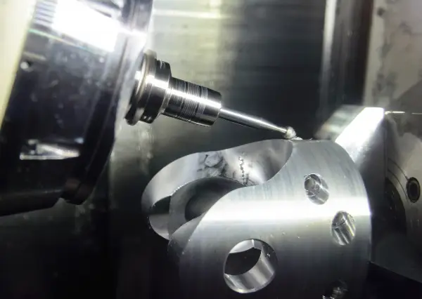
Ball nose end mills – For 3D contours and smooth curved surfaces.

Avoid standard two‑ or four‑flute metal-cutting tools – they generate too much friction and heat, causing melting.
CNC parameters that work
Use these starting values and adjust based on foam density:
| Foam type | Spindle speed (RPM) | Feed rate (IPM) | Depth of cut (inches) |
|---|---|---|---|
| EPS (low density) | 18,000 – 24,000 | 150 – 300 | 0.2 – 0.5 |
| XPS (medium) | 16,000 – 20,000 | 100 – 200 | 0.1 – 0.3 |
| Polyurethane (high density) | 12,000 – 18,000 | 60 – 120 | 0.05 – 0.15 |
Rule of thumb: Use the highest feed rate your machine can handle without losing step accuracy. Foam likes speed – slow feeds create rubbing, heat, and melting.
Step‑by‑step milling process
1. Secure the foam – Use double‑sided tape, vacuum table, or low‑hold hot glue. Avoid clamps that dent foam.
2. Set zero – Touch off on the top surface with a conductive tool or paper feeler. Foam compresses easily; do not force the tool.
3. Run a test cut – Cut a small pocket or profile in a waste area to verify settings.

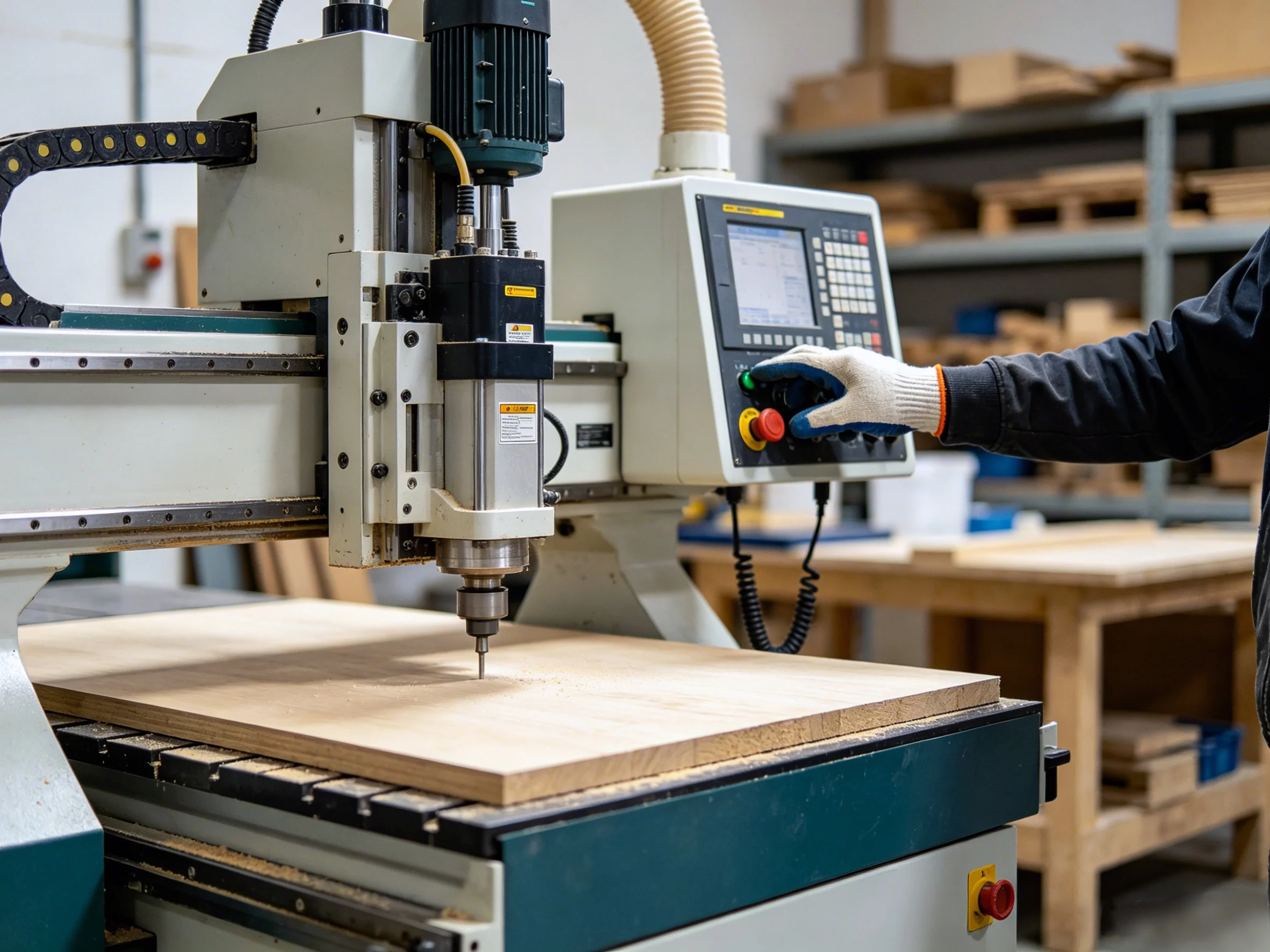
4. Apply dust collection – Foam chips and dust are static‑charged. Use a dust shoe connected to a vacuum.
5. Mill the part – For deep cuts, use ramping instead of plunging. Plunge directly only with a fishtail end mill.
Common problems and fixes
Melting or burrs → Increase feed rate or reduce spindle speed. Also check that the tool is sharp.
Fuzzy edges → Use a single‑flute O flute. If fuzz remains, a quick pass with a heat gun or light sanding removes it.
Tool pulling out of collet → Foam’s low cutting resistance can still cause vibration. Tighten the collet firmly and use a stub‑length tool if possible.
Static buildup → Ground your dust collection hose with a copper wire inside or use an anti‑static hose.
Safety and cleanup
Wear a dust mask – fine foam particles irritate lungs.
Do not use compressed air to blow off chips; it creates static and airborne dust. Vacuum instead.
Some foams (e.g., polyurethane) produce isocyanate dust when machined – always check the material SDS and use proper ventilation or a respirator.
For successful foam machining, start with the right tool. A single-flute O flute end mill is one of the most important tools for CNC milling foam because it clears chips well and reduces material tearing. For your first test, do not run too slowly. Start around 150 IPM and adjust only the feed or RPM if you see melting, sticking, or fuzzy edges. These problems usually mean heat is not being removed fast enough.
Always use dust collection during machining. Foam dust can block the cut line, create static issues, and affect operator safety. Once you find a stable combination of spindle speed, feed rate, and tool choice, save it as a separate foam tool library in your CAM software for future jobs. The core takeaway is simple: CNC milling foam is not about cutting slower. It is about fast feeds, single-flute tools, and proper dust removal. At YPMFG, these basic settings are checked first for foam prototypes and models to produce clean edges, fine details, and parts without melting.