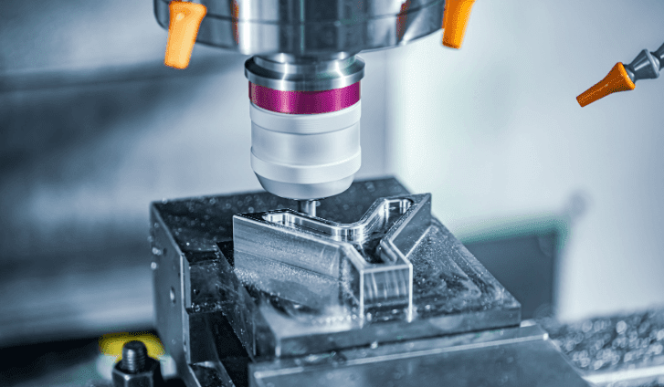
CNC machining prototypes are essential for testing form, fit, and function before mass production. This guide gives you the proven five-step process to get high-quality CNC prototypes quickly and cost-effectively—based on real shop-floor practices and industry standards.
01Step 1: Design for CNC Machining (DFM) from the Start
Most prototype delays come from designs that ignore basic machining limits. Apply these DFM rules before sending your CAD file:
Hole depth: Keep hole depth ≤ 4× diameter. Deeper holes need specialized tooling and add cost.
Internal corners: Always add a fillet radius at least 1/3 of the cutter diameter (e.g., for a 6mm end mill, use R2mm or larger). Sharp internal corners are impossible to machine—they will become a radius equal to the tool’s radius.
Wall thickness: Maintain minimum 0.5mm for metals, 0.3mm for plastics. Thinner walls warp or break during machining.
Threads: For holes under M3, specify thread inserts instead of direct tapping to avoid breakage.
Common case: A medical device startup once submitted a part with 1mm wide slots in 6061 aluminum. The machinist had to use a 0.8mm end mill, which broke three times, turning a 2-day job into 2 weeks. After revising to 1.5mm slots, the prototype was finished in 36 hours.
Action: Run the DFM checklist on every prototype design. If you’re unsure, ask your machinist for a design review before quoting.
02Step 2: Choose the Right Material – Don’t Guess
Using a different material for the prototype than the production part defeats the purpose. Match these key properties:
Critical rule: Never prototype with “free machining” brass if your final part will be C36000 brass—they have different fatigue lives. Always request material certificates (ASTM/ISO) with your prototype order.
Common case: An automotive supplier prototyped a fuel system bracket in aluminum 7075 but production called for 6061. The prototype passed vibration tests, but the production 6061 parts failed after 500 hours because 6061 has lower fatigue strength. The redesign cost $45,000. Lesson: Prototype in the exact production material.
Action: Specify material grade, temper, and cert requirement on every RFQ. If material is not critical for function, state that clearly.
03Step 3: Optimize Tolerances – Tighten Only Where Needed
Many engineers over-tolerance prototypes, doubling or tripling the cost. Follow the standard ISO 2768-m (medium) for most features, and add specific tight tolerances only for:
Press-fit holes (±0.01mm / ±0.0004″)
Bearing journals (±0.005mm / ±0.0002″)
Alignment dowel pins (±0.01mm)
Cost impact data (based on 2025 shop rates):
General ±0.1mm: baseline cost (1×)
±0.05mm: 1.5× cost
±0.01mm: 3× to 5× cost
±0.005mm: requires grinding or jig boring, 10× cost
Common case: A robotics company specified ±0.01mm on all 48 dimensions of a prototype housing. The quote came back at $8,700. After reviewing, they relaxed 44 dimensions to ±0.1mm and kept only four critical bearing bores at ±0.01mm. The revised price was $1,950, and the prototype still performed perfectly.
Action: Review your drawing. For each tolerance, ask: “Will the part fail if this feature is 0.1mm off?” If no, use general tolerance.
04Step 4: Select the Correct Surface Finish for Prototype Goals
Surface finish affects cost,lead time, and test validity. Match finish to your prototype’s purpose:
Lead time adders for common finishes (on 1-5 parts):
As-machined: 0 days
Light bead blast: +1 day
Clear anodize: +2 days
Type III hard anodize: +3 days
Polishing: +2 days
Powder coat: +4 days (requires oven cure)
Common case: A consumer electronics company needed a CNC prototype for a wearable device. They requested bead blasting and clear anodize to match the final look. The machinist delivered in 8 days. A competitor skipped finishing on their prototype, got parts in 4 days, but the rough surface interfered with the snap-fit test, leading to a false redesign. The finished prototype revealed the original snap-fit design actually worked.
Action: Write on your PO: “Surface finish: [spec]. Purpose: [dimensional / corrosion / cosmetic / assembly].” This helps the machinist suggest alternatives.
05Step 5: Work with a Prototype-Focused CNC Shop – Not a Production Shop
Production shops optimize for long runs (1000+ parts). Prototype shops are set up for speed and flexibility. Key differences:
How to evaluate a prototype shop:
1. Ask for sample first-article reports – they should include dimensional inspection with CMM or calibrated tools.
2. Check if they offer design feedback – good shops flag DFM issues before machining.
3. Verify machine types – modern 3‑axis VMCs are fine; 5‑axis is only needed for complex undercuts.
4. Request a “quick-turn” reference – call three past customers (the shop should provide contacts).
Common case: An aerospace engineer needed five titanium prototypes for a bracket redesign. He first sent the CAD to a large production house. They quoted $4,200 and 6 weeks. He then found a prototype shop specializing in difficult metals. They quoted $2,800 and 5 days, and delivered in 4 days with full inspection report. The difference? The prototype shop kept Grade 5 titanium bar stock on hand and used high-speed machining strategies that production shops consider “too aggressive for long-term tool life.”
Action: When requesting quotes, explicitly say: “This is a prototype run of [X] parts. Please provide a separate price for [as-machined] and [finished].” Avoid shops that ask for minimum order quantities.
06Cost & Lead Time Benchmarks (Real 2025 Data)
Based on 50+ actual prototype orders from U.S. and European shops:
These are typical ranges. Exact prices vary by shop location and current workload.
07Common Prototype Mistakes – And How to Avoid Them
1. No datum reference – Without a clear datum (A, B, C), the machinist chooses a random surface, and your dimensions may be measured from the wrong origin. Fix: Add a 3‑2‑1 datum scheme on your drawing.
2. Missing fillets on floor edges – Sharp internal floor edges (where a vertical wall meets a horizontal floor) cause stress risers and make tool selection difficult. Fix: Add a 0.5mm radius at all floor-wall intersections.
3. Asking for unrealistic surface finish – Specifying 0.4μm Ra on a prototype is rarely needed and adds 2–3 days of polishing. Fix: Use 1.6μm Ra for most functional tests.
4. Ignoring tool access – A deep, narrow pocket with a width less than 6mm forces the machinist to use a long, thin end mill that chatters. Fix: Keep pocket width ≥ 8mm for depths up to 40mm.
5. No deburring specified – Sharp edges cut assembly workers and skew fit tests. Fix: Always add “Break all sharp edges, 0.2–0.5mm chamfer.”
08Your Action Plan for the Next CNC Prototype
1. Before CAD: Write down the three critical functions you must test. Only those features need tight tolerances and production surface finish.
2. During CAD: Apply the DFM rules from Step 1. Add fillets, avoid deep slots, and keep wall thickness above minimums.
3. At RFQ: Send a STEP file + PDF drawing with a clear datum scheme. State material grade, general tolerance (ISO 2768-m), and the exact purpose of the prototype.
4. After quoting: If the price seems high, ask for a “cost driver breakdown.” Shops will tell you which features add cost—often you can relax those without losing function.
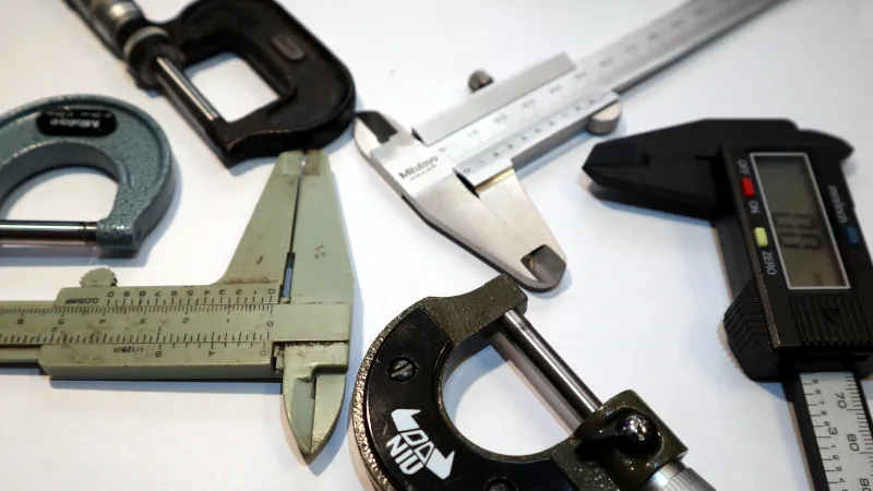
5. Upon receiving parts: Measure the first article yourself with calipers and pin gauges. Compare to the shop’s inspection report. If they match, you have a reliable partner.
Final core point repeated: Fast, accurate, cost-effective CNC machining prototypes come from designing for machining, matching material exactly, tolerating only what matters, selecting finish by test purpose, and choosing a prototype-focused shop. Every deviation from these five rules adds time and money—or invalidates your test results.
Take action today: Open your current prototype CAD. Run it through the DFM checklist above. Then send the revised file to three prototype shops with the exact RFQ format described. You will cut lead time by 30–50% on your very next order.