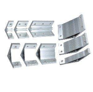
Metal housings, custom furniture, acrylic light panels, electronic components, decorative patterns — these products may serve different industries, but they share a common manufacturing backbone: CNC machining.
CNC (Computer Numerical Control) uses computer-driven systems to precisely cut, engrave, drill, and mill materials with minimal human intervention. At the heart of this digital manufacturing process is a low-profile yet essential element — the DXF file, which bridges design and production.
Table of Contents
1. What Is CNC?
CNC stands for Computer Numerical Control. It refers to a manufacturing technology that uses pre-programmed computer software to control the movement of machine tools.
Simply put, once a program is written, the machine can automatically perform operations such as cutting, engraving, drilling, and milling without manual control of each individual movement. This automation ensures high precision, repeatability, and efficiency.
Common CNC machining processes include:
- Laser cutting (for metal, acrylic, and sheet materials)
- Plasma cutting (commonly used for thick metal plates)
- CNC routing (woodworking, cabinet doors, decorative panels)
- CNC milling (precision mechanical components)
- Waterjet cutting (stone, composites, and heat-sensitive materials)
Despite their differences, all CNC machines share one thing in common: they don’t interpret drawings or verbal instructions. They operate strictly based on G-code — a programming language that tells the machine exactly how to move, where to cut, and at what speed.
This raises an important question:
Designers create parts using CAD software, which produces digital drawings. CNC machines, however, require G-code to operate.
So how do you bridge the gap between design and production?
The answer lies in the DXF file.
2. What Is a DXF File?
DXF stands for Drawing Exchange Format, a file format originally developed by Autodesk to enable data exchange between different design software platforms.
When it comes to transferring 2D geometry between CAD (design) software and CAM (manufacturing) software, DXF offers a major advantage. It efficiently stores essential geometric data such as:
- Lines
- Arcs
- Polylines and polygons
- Layers
Unlike raster image formats such as JPG, a DXF file contains vector data. This means it precisely defines geometry using mathematical coordinates rather than pixels. As a result, shapes, dimensions, and positions remain accurate and scalable, which is critical for CNC machining.
A DXF file helps the machine interpret:
- Which contours need to be cut
- Which features require drilling
- The exact shape and boundaries of the part
It’s important to note that a DXF file does not control the machine directly. Instead, it communicates geometric intent. It defines what the part looks like — not how it will be machined.
In the CNC workflow, the DXF file acts as a bridge between the designer’s digital drawing and the machine’s physical output. By translating design geometry into a format that CAM software can interpret, it enables efficient, high-quality, and repeatable production at scale.
3. The Role of DXF in the CNC Machining Workflow
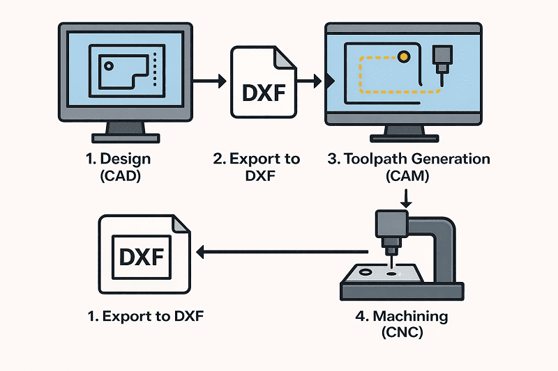
A standard CNC machining process typically follows these steps:
1. CAD Design
The process begins with the designer creating a part drawing in CAD software such as AutoCAD or SolidWorks. The geometry, dimensions, and features of the component are defined at this stage.
2. Exporting the DXF File
Once the design is complete, the drawing is exported as a DXF file. This format serves as a widely compatible intermediate file that most CAM systems can read and interpret.
3. Toolpath Generation (CAM)
The DXF file is then imported into CAM software such as SheetCAM or Aspire. Here, the programmer selects cutting tools, defines machining strategies, sets parameters, and generates the required G-code.
4. CNC Execution
Finally, the generated G-code is transferred to the CNC machine. The machine executes the programmed instructions and transforms the digital design into a physical part.
The DXF file plays a critical role between Step 2 and Step 3. It does not directly control the machine, but it provides the precise geometric data that CAM software uses to generate accurate toolpaths.
Without DXF (or a similar vector-based format), the transition from design to production would not be seamless or reliable.
4. Why Is DXF Essential in CNC Machining?
1. A Universal Industry Format
DXF is often considered the “universal language” of 2D manufacturing files. Nearly all major CAD and CAM software platforms support DXF, making it one of the most widely compatible file formats in the industry.
Regardless of which CAD software is used for design, as long as it can export a DXF file, most CAM systems can import and process it without compatibility issues. This seamless interoperability improves collaboration between designers, engineers, and machinists.
2. High Geometric Accuracy for Toolpath Generation
CNC machining demands extreme precision. Even a deviation of one millimeter can result in a rejected part.
Because DXF is a vector-based format, it stores precise geometric data such as:
- Exact line start and end points
- Arc radii and center points
- Closed polyline and polygon definitions
This mathematical accuracy makes DXF ideal for generating reliable cutting paths and tool movements in CAM software.
3. Layer Support for Process Differentiation
DXF files support multiple layers, allowing different machining operations to be clearly organized within the same drawing.
For example:
- Outer contour – cut
- Inner holes – drill
- Engraving lines – engrave
- Reference marks – ref
By assigning different operations to separate layers, programmers can quickly define machining strategies inside the CAM system. This reduces programming time, minimizes errors, and increases production efficiency.
In short, DXF is not just a file format, it is a structured, manufacturing-ready data bridge that ensures accuracy, compatibility, and efficiency in CNC production.
5. Practical Examples of DXF in CNC Applications
1. Laser Cutting Metal Parts
A customer submits a DXF file containing the profile of a metal plate with multiple holes.
After importing the file into CAM software, the programmer defines inside and outside cuts, piercing points, lead-ins, and cutting parameters. Within minutes, the system generates the toolpaths required for production.
The result: fast setup, accurate cutting, and efficient batch manufacturing.
2. CNC Routing Decorative Wood Panels
A designer creates a full decorative pattern in CAD and exports it as a DXF file.
The file is then imported into routing software, where the operator selects the appropriate tool and sets engraving depth and machining strategy. The CNC router precisely transfers the digital design onto a physical wooden panel.
This workflow ensures consistency, repeatability, and high-quality surface finish.
3. Nesting Multiple Parts for Material Optimization
In sheet metal or panel processing, manufacturers often receive multiple DXF files — each representing a different part.
These files can be arranged (nested) onto a single large sheet to maximize material usage. The optimized layout is then processed in one cutting cycle, reducing scrap and lowering production costs.
This nesting capability is one of the major efficiency advantages of using DXF files in CNC workflows.
These examples demonstrate how DXF files streamline the transition from digital design to physical production across various CNC applications.
6. What DXF Is Not
A DXF file is a drawing format, it is not a machine control program.
It tells the system what the part looks like, but it does not contain machining parameters such as:
- Tool diameter
- Feed rate
- Cutting sequence
- Tool compensation
- Spindle speed or depth settings
These manufacturing parameters are defined later in the CAM software, where toolpaths are created based on the geometric data contained in the DXF file.
In simple terms, the DXF file is the blueprint while G-code is the script that directs the machine’s actions.
7. Conclusion
DXF plays an essential role in the CNC machining workflow. It is not the initial design tool, and it is not the final machine instruction. Instead, it serves as the critical bridge between the two.
It translates human design intent into structured geometric data that manufacturing systems can interpret.
If G-code is the language spoken by CNC machines, then DXF is the structured expression of human design thinking. It transforms drawings into manufacturable data and ultimately turns digital concepts into physical reality.