In precision thin-sheet processing, have you ever been troubled by part deformation and uncontrollable accuracy?
Whether it’s lightweight components in aerospace or ultra-thin elements in electronic devices, machining thin-sheet parts invariably faces a core challenge: how to maintain dimensional stability and surface integrity under the combined forces of cutting and clamping? Drawing from multiple real-world machining cases, this article systematically outlines comprehensive process solutions, from simple thin plates and complex structural components to ultra-thin foils. By optimizing clamping designs, adjusting machining strategies, and incorporating flexible support methods, we successfully controlled machining deformation while achieving dual improvements in quality and efficiency.
Introduction
With the widespread application of precision thin-plate components in aviation, aerospace, satellite, electronics, and nuclear industries, their high-efficiency and high-precision machining has become critically important. Controlling machining and clamping deformation has long been a major challenge in precision thin-plate component processing. This article presents machining solutions for simple thin plates, complex thin plates, and ultra-thin plates based on practical case studies, ensuring compliance with product precision requirements.
Simple Thin Sheet Metal Part Machining
Simple thin sheet metal parts are typically small in size with relatively simple shapes. During blanking, they cannot be cut as individual pieces due to their small size, making them unsuitable for clamping with universal fixtures like vices. Generally requiring finishing on six surfaces, multiple clamping operations can easily introduce clamping errors, compromising both machining efficiency and quality. Through research and exploration, the following machining method has been developed.
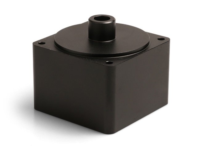
1) During blanking, cut a single large plate to produce multiple workpieces. Fabricate a fixture plate (see Figure 1), clamp the plate securely onto the fixture plate using a clamping plate, and precision-mill both end faces.
2) Utilize adjustable-length clamping plates to provide auxiliary clamping for the workpiece, preventing it from detaching from the base plate and causing tool collisions upon completion of milling. The toolpath for precision milling the workpiece’s outer contour is shown in Figure 2.
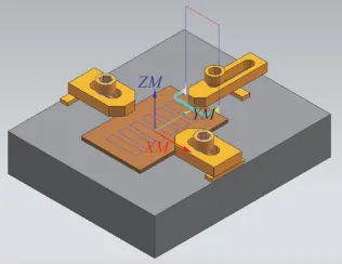
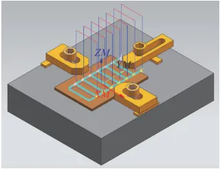
Figure 2. Machining Path for the Outline of a Precision-Milled Workpiece
Machining Complex Thin Sheet Metal Parts
Machining complex thin sheet metal parts involves multiple elements, typically including hole patterns, slots, or steps. During processing, features like through holes or slots can be effectively utilized to create auxiliary holes. Screws, washers, and bosses on the fixture are employed to clamp and position the part. By shifting the clamping location, complete machining of all areas is ensured while maintaining consistent clamping throughout the process. The machining plan for a specific complex thin-plate part is outlined below.
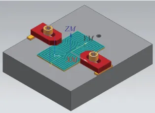
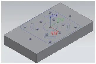
1) Design and fabricate a fixture plate based on the part’s final machined profile (see Figure 3). Pre-drill holes for locking screws and clamping plate screws on the fixture plate.
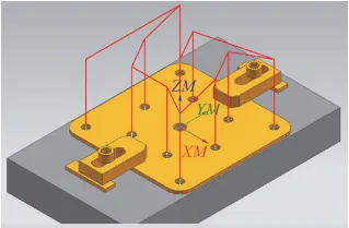
2) Clamping for the first machining operation is shown in Figure 4. Use clamping plates to secure the workpiece onto the fixture plate, ensuring it is roughly positioned correctly. The holes on the pre-machined workpiece (with machining allowances retained for hole dimensions) should be clamped.
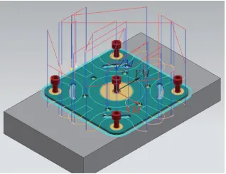
3) For the second machining operation, clamp the workpiece as shown in Figure 5. Secure the workpiece by tightening the four peripheral screws and the single central screw. Remove the side clamping plates, then perform precision milling on the workpiece’s top face, holes, slots, and outer contour.
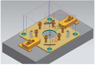
4) For the third machining operation of the part, clamping is performed as shown in Figure 6. Remove the original screws and install six screws on the inner side. Use the two clamping plates at both ends to assist in tightening. Finish mill the interference area on the upper end face from the previous step, finish mill the four peripheral holes and the central large hole, and complete the machining.
This solution addresses the challenge of clamping complex thin-plate workpieces. For thin-plate parts ranging from 3 to 5 mm thick, it enables simultaneous processing of multiple pieces in a single setup. This approach not only ensures consistent product quality but also significantly boosts manufacturing efficiency.
Ultra-thin sheet metal parts processing
Ultra-thin sheet metal parts have thicknesses ranging from 0.05 to 0.15 mm, typically made of stainless steel or non-ferrous metals. They are commonly used as washers or gaskets. Due to their extreme thinness, traditional mechanical clamping methods cannot be employed during machining. Given their structural characteristics, raw materials are procured as plates matching the part thickness. These are manually cut to size and secured using upper and lower clamping plates with screws for multi-layer locking. Alternatively, they are fixed via welding under clamping force. A machinist drills through-holes, after which wire EDM machines are employed for processing. The wire is first threaded through the through-holes to precision-cut the inner hole, followed by threading from the exterior to precision-cut the outer contour. The specific workflow is as follows:
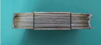
1) Clamp the cut plate material between upper and lower pressure plates (see Figure 7), securing it via welding or screws.
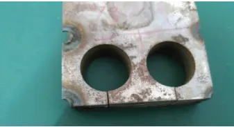
2) For electrical discharge machining using wire EDM, thread the wire through the central hole first to precision-cut the part’s internal bore. Then thread the wire from the exterior to precision-cut the part’s external contour. The resulting internal bore and external contour after wire cutting are shown in Figure 8.
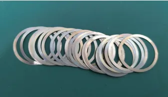
Through the above operations, precision machining of ultra-thin plate components can be achieved. Figure 9 shows the finished product, with a component thickness of 0.1mm.
The thin plate components in this article are too delicate for conventional mechanical clamping methods. To address this, several efficient and practical machining solutions have been developed. These solutions have been rigorously validated through repeated testing in actual production. By employing appropriate clamping techniques and machining methods, they effectively resolve the challenges of machining ultra-thin plate components and mitigate clamping deformation issues in complex thin plate parts. This approach reliably ensures the machining quality of thin plate components while significantly enhancing production efficiency.
YPMFG Experts:
The thin sheet metal parts in this example are too delicate for conventional mechanical clamping methods. Consequently, several efficient and practical machining solutions were developed. Through repeated verification and process refinement during actual production, a rational clamping approach was established. This enables single-setup blanking and multi-part machining of thin sheet metal components, effectively resolving clamping and deformation issues.
The article highlights a multi-layer clamping method for machining ultra-thin sheet metal parts. Raw materials are procured as sheet stock matching the part thickness, manually cut to size, then secured using upper and lower clamping plates with screws for multi-layer locking. Alternatively, parts are welded in a clamped state for fixation. Following this, machinists drill threaded holes, perform wire cutting for internal holes and outer contours to meet design specifications. This approach effectively controls deformation in ultra-thin sheet metal parts, enhancing machining accuracy and production efficiency.