
Quick answer:
Custom sheet metal fabrication transforms flat metal coils into precision parts through cutting, bending, joining, and finishing. It is the most widely used manufacturing method for electronic enclosures, automotive brackets, medical housings, and industrial equipment components. When working with a capable CNC machining and fabrication partner, you gain access to iterative prototyping, full engineering reviews, and scalable production from prototype to high-volume runs without sacrificing tolerances or surface quality.
Many engineers and procurement managers approach custom sheet metal fabrication with uncertainty. The process sounds straightforward, yet the variables are numerous. Material choice, tolerances, surface treatment, tooling strategy, and quality documentation all affect lead time and unit cost. A misstep in the design phase can double the final price or create unresolvable assembly issues. This guide addresses the practical questions that matter most when sourcing sheet metal parts for production or NPI projects.
Core Processes Used in Sheet Metal Fabrication
Sheet metal fabrication is not a single process. It is a combination of discrete operations that transform raw coil or blank stock into finished assemblies. Understanding which processes apply to your part determines both feasibility and cost structure.
The primary operations include laser cutting, punching, bending, welding, and surface finishing. Each step introduces distinct constraints that designers must account for before releasing drawings for production.
Laser Cutting
Laser cutting uses a focused beam to slice thin to medium-gauge metal with high precision. Fiber laser systems currently dominate the market for steel and aluminum parts up to approximately 25 mm thickness. The achievable tolerance typically falls within ±0.1 mm for repeatable production runs.
Key advantages include minimal kerf width, clean edges that often require no secondary finishing, and the ability to produce complex geometries without dedicated tooling. The main limitation is edge quality on reflective materials like copper and brass, which may require additional processing or alternative methods.
Turret Punching
Turret punching uses a press and a rotating tool station to create holes, slots, and formed features. It remains cost-effective for high-volume hole patterns and simple cutouts, especially when the part design relies heavily on repeated geometric features.
Modern CNC turret punch presses combine punching with mild forming operations such as embosses, nuts, and tapped holes. The process produces consistent results across large batches but struggles with complex contours that laser cutting handles more efficiently.
Bending and Forming
Bending shapes flat cut parts into three-dimensional forms using press brakes with interchangeable tooling. The bend allowance calculation directly affects final dimensional accuracy and must be accounted for in the flat pattern developed during the design stage.
Designers should specify minimum bend radius values appropriate to the material thickness. A rule of thumb is that the minimum internal bend radius equals the material thickness for mild steel and increases for harder alloys. Violating these guidelines causes cracking, springback variability, and dimensional drift during production.
Welding and Joining
Fabricated sheet metal assemblies frequently require welding to join multiple components. Common methods include MIG welding for carbon steel, TIG welding for aluminum and stainless steel, and spot welding for thin-gauge overlapping joints.
Joining strategy affects both structural integrity and cosmetic appearance. Weld distortion can shift adjacent features out of tolerance, requiring post-weld machining or rework. Good design practice separates weld accessibility from critical mating surfaces and specifies weld types that align with functional requirements rather than aesthetics alone.
Surface Finishing Options
Surface finishing protects fabricated parts from corrosion, wear, and environmental exposure while meeting aesthetic or regulatory requirements. Common treatments include powder coating, electrostatic painting, anodizing for aluminum,plating, and passivation for stainless steel.
Each finishing method imposes different design constraints. Powder coating adds material thickness that affects assembly clearances. Anodizing cannot be applied selectively to hardened or welded areas without masking. Specifying finish requirements early prevents costly rework and ensures compliance with industry-specific standards.
Material Selection for Custom Sheet Metal Parts
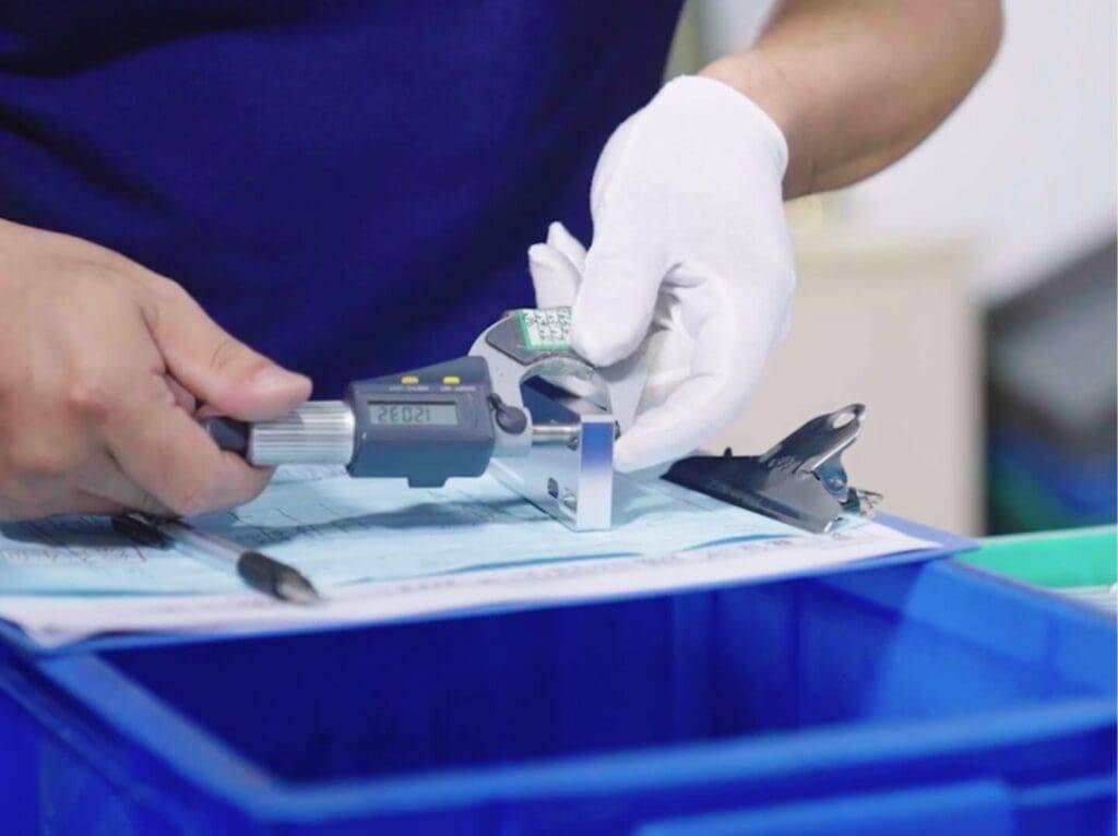
Material selection is one of the most consequential decisions in the fabrication process. It influences machinability, strength, weight, corrosion resistance, and cost. Choosing the wrong alloy often leads to premature failure or unnecessary expense.
Common Sheet Metal Materials
Mild steel (low-carbon steel) remains the most widely used material for general-purpose fabrications. It offers excellent formability, weldability, and competitive pricing. Typical grades include ASTM A36 for structural applications and Cold Rolled Steel (CRS) for tighter tolerance parts.
Stainless steel provides superior corrosion resistance and maintains strength at elevated temperatures. Grade 304 is the standard choice for food, medical, and architectural applications. Grade 316 offers enhanced resistance to chlorides and is preferred in marine and chemical environments. Both grades require specific finishing protocols to preserve their corrosion-resistant properties.
Aluminum is selected for lightweight applications requiring good strength-to-weight ratios and natural corrosion resistance. Series 5000 offers excellent formability and weldability for architectural and transportation uses. Series 6000 responds well to anodizing and is common in consumer electronics housings.
Material Thickness and Gauge Systems
Sheet metal thickness is expressed in both decimal inch or millimeter measurements and gauge numbers. The gauge system varies by material type, which creates frequent confusion during procurement. A 16-gauge mild steel sheet measures approximately 1.5 mm, while 16-gauge aluminum measures about 1.4 mm.
When requesting quotes or specifying drawings, always use decimal or metric dimensions. Relying on gauge numbers alone introduces ambiguity and can result in receiving parts that do not meet functional requirements.
Design for Manufacturability in Sheet Metal
DFM principles reduce fabrication cost, shorten lead time, and prevent production failures. Most issues arise from designs that ignore the practical limitations of cutting, bending, and assembling sheet metal components.
Critical DFM Guidelines
Maintain adequate hole spacing from bend lines. Holes placed too close to a bend will deform during forming and shift out of tolerance. A minimum distance of three times the material thickness from any bend line is generally safe for standard forming operations.
Avoid sharp internal corners in laser-cut parts. While modern lasers can produce near-square corners, sharp internal angles stress concentrate during bending and increase the risk of cracking. Adding a small relief notch at corner junctions improves both manufacturability and part durability.
Standardize hole sizes and fastener types wherever possible. Non-standard hole diameters require special tooling or secondary drilling operations that increase per-unit cost. Standard drill sizes and tapped hole specifications align with common fastener inventory and reduce assembly errors.
Tolerance Specification Best Practices
Specifying overly tight tolerances on sheet metal parts creates disproportionate cost increases. Sheet metal fabrication inherently involves thermal expansion, springback, and clamp variation. Target realistic tolerances based on functional requirements rather than ideal conditions.
Typical achievable tolerances for laser-cut parts are ±0.1 mm for dimensions under 100 mm and ±0.2 mm for larger features. Bending tolerances typically range from ±0.5 mm to ±1 mm depending on part geometry and machine capability. Coordinate with your fabrication partner during the design phase to validate feasibility before finalizing drawings.
Quality Standards and Documentation
Quality documentation separates professional fabrication shops from opportunistic job shops. Proper documentation ensures traceability, supports regulatory compliance, and reduces disputes during incoming inspection.
Common Quality Certifications
ISO 9001 is the baseline quality management standard recognized globally. It ensures that a fabricator maintains documented procedures for design control, material traceability, inspection, and corrective action. Many procurement teams require ISO certification as a minimum qualification for supplier approval.
Industry-specific certifications may be required depending on your application. Medical device manufacturers often require ISO 13485 compliance. Aerospace and defense contracts may demand AS9100 certification. Food and beverage equipment suppliers may need NSF or 3-A sanitary compliance.

Inspection and Test Reports
Reputable fabrication providers supply inspection reports that include first-article inspection results, material certificates, and dimensional verification data. These documents should reference the original drawing revision and clearly indicate measurement methods and equipment calibration status.
Requesting ASME Y14.5 GD&T compliant drawings with proper feature control frames ensures that inspection requirements are unambiguous. Part drawings should specify datum references, tolerance zones, and surface finish requirements rather than relying on generic notes.
Cost Factors in Custom Sheet Metal Fabrication
Understanding what drives fabrication cost helps procurement teams evaluate quotes accurately and make informed design trade-offs. Unit price is rarely the most important factor in the total ownership equation.
Primary Cost Drivers
Material cost represents a significant portion of the base price, particularly for stainless steel and aluminum alloys. However, material waste from nest optimization and scrap recovery often offsets a portion of raw material expense. A skilled fabricator maximizes material utilization through intelligent nesting software and strategic part arrangement.
Setup and programming time affect low-volume orders disproportionately. High-mix, low-volume production requires frequent tool changes, program reloads, and setup adjustments. Volume production amortizes these fixed costs across more units, reducing per-part pricing significantly.
Secondary operations such as tapping, welding, threading, and finishing add labor and equipment time. Each additional operation increases both direct cost and scheduling complexity. Consolidating features into fewer operations through thoughtful design reduces total manufacturing time.
Hidden Cost Risks
Design revisions after tooling is set up generate change order charges that rarely appear in the initial quote. Confirming design freeze before production begins prevents unexpected costs and schedule delays.
Incomplete or ambiguous drawings lead to clarification delays and potential rework. Providing complete geometric dimensioning and tolerancing, surface finish specifications, and material callouts eliminates guesswork during quoting and production.
rushed timelines often require premium shipping, overtime labor, and expedited material procurement. Planning lead time into the project schedule avoids these surcharges and ensures proper quality control procedures can be followed without compression.
Comparing Fabrication Approaches
Different fabrication methods suit different production volumes, complexity levels, and performance requirements. Selecting the wrong process for your application wastes budget and compromises part quality.
The optimal approach often combines multiple methods within a single workflow. A typical production sequence might include laser cutting for profile creation, turret punching for high-density hole patterns, press brake forming for bending, and TIG welding for final assembly. Each step should be evaluated for efficiency and quality impact.
YPMFG supports projects across this full spectrum, selecting the most appropriate process combination based on your part geometry, material, volume, and performance requirements. Engineering review is available before production begins to validate manufacturability.
How to Choose a Sheet Metal Fabrication Partner
Selecting the right fabrication partner requires evaluating technical capability, quality systems, communication responsiveness, and production scalability. The lowest quote is rarely the optimal choice for production-critical components.
Key Evaluation Criteria
Verify that the supplier possesses the CNC machining and fabrication equipment necessary for your part requirements. Press brake tonnage, laser cutting envelope size, and welding capability directly determine what geometries can be produced in-house versus subcontracted.
Assess the quality documentation system. Request sample inspection reports, material traceability records, and process control documentation. A supplier that cannot provide these documents consistently signals inadequate quality management practices.
Evaluate engineering communication during the quotation process. Prompt responses, constructive DFM feedback, and clarification questions indicate a partner invested in producing parts that meet your specifications rather than simply accepting orders.
Red Flags to Avoid
Suppliers who accept drawings without review, refuse to discuss tolerance feasibility, or consistently underquote relative to market rates may lack the technical depth required for complex fabrications. These behaviors often result in late deliveries, quality disputes, and hidden change orders.
Excessive subcontracting without oversight creates traceability gaps and quality inconsistency. Understanding which processes are performed in-house versus outsourced helps you assess risk and accountability throughout the production chain.
Common Questions Buyers Ask About Custom Sheet Metal Fabrication
What is the difference between prototype and production sheet metal fabrication?
Prototype fabrication prioritizes speed and design validation over per-unit cost. Production fabrication optimizes for consistency, throughput, and unit price reduction through process refinement and tooling investment. The transition between phases should be managed collaboratively to ensure design maturity before volume commitment.
How long does custom sheet metal fabrication typically take?
Lead time depends on part complexity, material availability, quantity, and current shop workload. Simple laser-cut parts may ship within days. Complex welded assemblies requiring multiple operations and finishing typically require two to six weeks. Establishing clear timelines during the quotation phase prevents schedule surprises.
Can you fabricate parts from my existing drawings?
Yes, provided the drawings contain sufficient detail for manufacturing. Complete drawings should include material specification, thickness, tolerance callouts, surface finish requirements, and any applicable industry standards. Incomplete documentation requires clarification cycles that extend lead time and may reveal design gaps needing resolution before production can begin.
What quality documentation will I receive with my order?
Standard documentation includes material certificates, first-article inspection reports, dimensional verification data, and finishing specification confirmation. Additional documentation such as NCR records, calibration certificates, and process journey logs should be specified during ordering if required by your quality management system or industry regulations.
How do I validate that a fabricated part meets my specifications?
Incoming inspection should verify critical dimensions using calibrated measuring equipment, confirm material composition through positive material identification when required, and assess surface finish against approved reference standards. Coordinate acceptance criteria with your supplier before production begins to align expectations and reduce inspection disputes.
What happens if a part fails inspection?
Reputable fabrication providers maintain defined nonconformance handling procedures. Defective parts are documented, quarantined, and either repaired, reworked, or replaced according to agreed terms. Understanding the dispute resolution process and warranty provisions before ordering protects your project schedule and budget.
Making a Better Long-Term Decision
Custom sheet metal fabrication delivers versatile, cost-effective solutions for a wide range of engineering applications. Success depends on thoughtful design, informed material selection, realistic tolerance specification, and partnership with a capable fabrication provider. The decisions made during the engineering and sourcing phase establish the foundation for production quality, delivery reliability, and total cost performance.
YPMFG provides CNC machining and parts manufacturing services that integrate sheet metal fabrication with complementary precision processes. Our team offers engineering evaluation, custom solution development, and comprehensive support from initial consultation through production delivery. You can send your specifications to YPMFG for review or request a detailed quotation for your next project.