Dear classmates, hello.
Today, we plan to tell you about a good pair that always goes together – CNC and CAD. If manufacturing parts is regarded as a wonderful journey, then CAD is the "treasure hunt map" full of dreams, and CNC is the loyal and reliable "treasure hunt craftsman". They work hand in hand to transform the novel ideas in their minds into real objects that shine with metallic luster before their eyes.
So, how do such partners carry out their work? Don't be impatient, let us slowly uncover their mysterious covering.
01CAD: Talking “design drawing paper”
1.1 The first stroke of a dream
Think about the situation. You are holding a piece of drawing paper with breathing properties. With a light tap, you can draw a straight line; with a random drag, you can create a rounded arc. This is the unique charm of CAD (computer-aided design) software.
It is not only a drawing tool, but also a "language translator" for designers .
In its world, points, lines, and surfaces have all learned to sing.
Every dimension hides the rigorous heartbeat of engineers.
Do you understand? A survey of people who have just started learning found that more than 70% of the errors that occur in processing actually have hidden dangers in the design stage. This is like building a house. If the pillars in the drawings are offset by one centimeter and are not discovered until the brick walls are built, the cost of demolition and modification will be very high.
A common situation is that a classmate carefully designs an extremely beautiful shell with very graceful curves and a particularly avant-garde shape. But when he was about to hand the file to the CNC machine with great joy, the machine "strike". Why is this? It turns out that he drew an inner sharp angle that is infinitesimal in theory, but in reality the tool has a round head with a radius. How can a round knife cut straight corners?
1.2 Let the drawings understand “human language”
Therefore, the mission of CAD is very clear. It must not only draw beautiful shapes, but also consider a question, that is: Can my partner CNC understand my mind?
From "approximately" to "accurately", say goodbye to "almost", and embrace the tenacity and persistence of 0.01 mm.
From "flat" to "three-dimensional" : Inject height into lines and give graphics thickness.
Starting from "abstract" and moving towards "concrete", the imagination stored in the mind is broken into concrete and clear processing indicators step by step, step by step, and then formed into instructions.
> Keyword integration: design intent
The so-called "design intention" is related to what function you expect this part to achieve in the end, how much force it will withstand, and which brother parts it will cooperate with. CAD drawings will record this intention, and CNC is responsible for faithfully transforming it into reality. Without clear intentions, even the most beautiful model is just a castle in the air.
When CAD prepares the treasure map filled with "design intentions", a relay spanning virtuality and reality is about to officially begin. So, how does the CNC craftsman understand the drawings?
02CNC: the tireless “magical craftsman”
2.1 From lines to trajectories
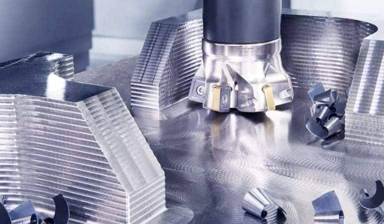
The CNC machine tool named "Computer Numerical Control Machine Tool" has a pair of eyes that can see through the beauty of data, and it also has a pair of hands that are powerful, dexterous and precise.
It never complained or cried tired.
It can work for days and nights and still maintain the same energy.
Every turn it makes is amazingly precise.
CNC cannot read sketches drawn by humans, but it can "understand" files exported by CAD, which are generally G codes. In this mysterious string of codes, all instructions such as "move the X axis forward 10 mm", "the spindle speed is 8000 rpm", "change the tool", etc. are recorded.
The following is the rewritten version: A common situation is that another student learned the lesson and specially designed all internal corners to be R3 (radius 3 mm) fillet during design, and marked clear and followable tolerance requirements. He then entered the program into the CNC machine and pressed the start button. As a result, the machine seemed to dance lightly, and the cutting fluid seemed to spray out like a drizzle. Twenty minutes later, a shell was born that was smooth, precise, and fit the design perfectly.
2.2 The “iron rule” of craftsmen
In the world of CNC, there are several iron laws that you need to keep in mind:
1. Combining hardness and softness : the tool must be harder than the material, and the thought must be thinner than a hair.
2. Work step by step : from rough machining to fine machining, like a painter from laying out large blocks of color to tracing details.
3. Feedback closed loop : The machine is processing, you can observe it, but do not disturb it easily.
> Keyword integration: processing path
The processed path is the "footprint" left by the CNC tool walking on the material, including whether it is in a straight line or around an arc, and whether it is milling from top to bottom or back and forth. Different paths are like different walking postures, which will directly affect the processing efficiency, surface finish and tool life. Optimizing the path is equivalent to equipping the craftsman with a pair of shoes that fit the best.
I would like to ask, do you think that CNC can achieve everything by itself as long as the CAD drawing is excellent? In fact, this is not the case, and conflicts sometimes arise between them.
03 Frequently Asked Questions: What to do when CAD and CNC "quarrel"?
Q1: Why does my perfect CAD model look like it has been gnawed by a dog when processed by CNC?
A: Check whether the model units are consistent! Conversion from imperial to metric reduces the dimensions by a factor of twenty-five point four. Must be unified into millimeters.
Q2: CNC tools always leave uncut “remnant material” in a small corner. What’s going on?
A: That is a problem of "root cleaning". There is a situation in the CAD model that allows infinitely small corners, but the fillet tool cannot enter it. During the design, it is necessary to reserve space for the tool to avoid.
Q3: My thin-walled parts deform after processing. Is the CAD design wrong?
A: Although the design is correct, it is too "ideal". Nature does not like hanging and thin sheets. Strengthening ribs need to be added, or the clamping method needs to be changed.
Q4: There are so many export formats for CAD software, which one should I choose for CNC?
A: The most versatile ones are the STEP format or IGES format. _Don't use the STL format_ because it turns smooth surfaces into ugly little triangles.
Q5: Every time I change a little bit of the design, I have to generate the CNC tool path from scratch. It’s very troublesome. Is there a shortcut?
A: Using the "feature recognition" function, the CAM software can automatically find the holes or slots you have modified, and only update the modified parts, not all recalculations.
Look, the answers to these questions actually all point in the same direction: you have to be as familiar with the palm of your hand, familiar with the degrees of freedom of CAD and the boundaries of CNC.
Think about it: the last time you designed a part, before you put pen to paper, did you ask yourself: "If I were that milling cutter, how would I get into this corner?"
04Suggestions for a journey together
If CAD and CNC are a natural pair, then as their owners, how can we make them achieve better collaboration with each other?
Here is a small action guide for you:
Start Easy: Don't try the "Eiffel Tower" challenge at the beginning. First draw a block and try to process it. Experience the sound and texture of materials as they are cut.
Establish a "check-check-list" :
[ ] Is the model completely closed (no broken surfaces)?
[ ] Are the internal corners rounded (larger than the tool radius)?
[ ] Is the thickness of the thin wall greater than the minimum limit of the material?
[ ] Are dimensional tolerances clearly marked?
Embracing simulation is implemented, and before the CNC is allowed to carry out real cutting of precious materials, it is "virtually run" in the software. This is just like the pre-war sand table deduction, which can detect more than 90% of collision and overcut problems.
> Keyword Integration: Material Response
Aluminum alloys prefer high speeds and large cutting knives, while acrylic is afraid of high temperatures and requires sharp single-edged knives and "meter-pecking" downward cutting. Material is not a passive "lamb to be slaughtered", it has its own temperament. Understanding the response of materials lies in understanding the steady or crisp "singing" of CNC machining.
05 Written at the end: One handshake, infinite possibilities
Remember the metaphor at the beginning about the treasure map and the craftsman?
Now, you already know: CAD is the treasure map containing many possibilities, while CNC is the loyal and reliable craftsman who can transform "possibility" into "reality". Between the two of them, there is no one who is more important, only mutual success.
CAD gives CNC wisdom .
CNC gives life to CAD.
Don't let the design stay on the screen, and don't let the machine idle without soul instructions. Next time, when you open the CAD software and draw the first line, please remember that the end point of this line should be on the CNC processing table, shining with the light of the creator, and that is the shape you give to the world with your own hands.
> Keyword integration: human-machine dialogue
At first there was a vague idea, then regular lines appeared in CAD, and then there were flying debris during CNC cutting. This whole process is a profound and poetic human-machine dialogue. When you ask questions, it is design, and when the machine answers, it is processing. The right or wrong answer depends not only on the machine, but more importantly, in your heart.
I pray that you will enjoy every step of the process from conception in your mind to touching it with your own hands. I hope this pair can be called a good companion and can accompany you into a shining stage of learning. If you encounter difficulties along the way, don't forget that the universal "checklist" and the clear "planning intention" in your heart are always your most trustworthy guides.
I wish you happy designing and smooth processing!
——A friend who always cheers you on


