This guide covers the main methods of aluminum profile processing, including cutting, drilling, CNC machining, bending, welding, and surface finishing. Aluminum profiles may look easy to process, but poor control of cut squareness, hole position, tolerances, or surface protection can quickly lead to poor assembly fit, scratches, deformation, or dimensional errors.
In real projects, it is better to confirm the aluminum grade, profile section, length tolerance, hole requirements, and surface finish before production starts. At YPMFG, these details are also checked early in aluminum profile processing projects to reduce rework and keep part quality stable. This guide explains common processing methods, achievable tolerances, and key quality control steps to help you avoid typical defects.
01Core Methods for Processing Aluminum Profiles
Every processing workflow starts with selecting the right method for the profile shape (e.g., T-slot, angle, tube, or custom extrusion) and the intended application (structural frames, enclosures, heat sinks, etc.). Below are the most widely used industrial methods.
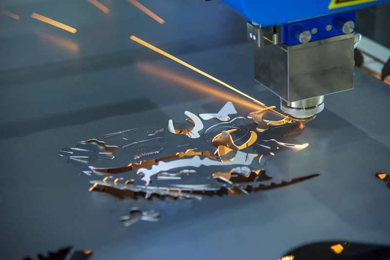
1.1 Cutting
Common equipment: Automatic miter saws (with carbide-tipped blades), cold saws, and band saws.
Typical tolerance: ±0.5 mm for standard cuts; ±0.2 mm with precision stop systems.
Case example – a common workshop issue: A manufacturer cut 50 aluminum profiles using a standard abrasive saw. Result: burrs and uneven edges that required manual deburring. Switching to a carbide-tipped cold saw (10-inch, 80-tooth) eliminated burrs and reduced post-processing time by 70%.
Critical rule: Always use blades designed for aluminum (negative rake angle, non-ferrous metal lubrication). Never use wood-cutting blades – they cause chip welding and dangerous kickback.
1.2 Drilling & Tapping
Hole types: Through holes, blind holes, countersinks, and threaded holes.
Tapping tolerance: ISO 6H for standard threads (e.g., M4, M5, M6). Use spiral point taps for through holes and spiral flute taps for blind holes.
Common defect & fix: Aluminum is sticky – chips easily clog the tap. Solution: use a 5-8% concentration of water-soluble cutting fluid and peck-tap (advance 2-3 threads, then retract).
1.3 CNC Machining (Milling & Routing)
Applications: Creating slots, pockets, complex contours, and precise end-machining (e.g., notches for corner brackets).
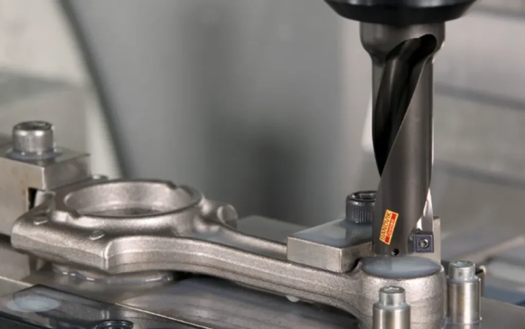
Achievable tolerance: ±0.05 mm for 3-axis CNC mills under controlled conditions.
Tool selection: Single-flute or two-flute carbide end mills with polished flutes (optimized for aluminum). Typical spindle speed: 12,000–18,000 RPM for 3 mm tools.
Case example – avoiding chatter: A fabricator tried to mill a 5 mm slot in a 6061 profile using a four-flute steel tool. Result: severe chatter and rough surface. Replacing with a two-flute polished carbide tool at 14,000 RPM eliminated chatter and produced a mirror-like finish.
1.4 Bending (Section Bending)
Methods: Rotary draw bending (for tight radii) and three-roll push bending (for large radii).
Minimum bend radius (without wrinkling or cracking): For 6063-T5 profiles, the safe radius is 3× the profile’s outer width. For example, a 40 mm wide profile requires at least 120 mm bend radius.
Critical preparation: Fill the profile with mandrel or sand to prevent collapse. Always test on scrap pieces first.
1.5 Welding (TIG & MIG)
Suitability: Most 6xxx series (6061, 6063) are weldable. 2xxx and 7xxx series are generally not recommended for structural welding.
Filler metal: 4043 or 5356 alloy. 4043 offers better crack resistance for anodized finishes.
Common defect – porosity: Caused by hydrogen absorption from moisture or oil. Solution: degrease the weld area with acetone and store filler rods in a dry cabinet (below 50% relative humidity).
1.6 Surface Finishing (Anodizing & Powder Coating)
Anodizing (Type II or Type III) : Provides a hard, corrosion-resistant oxide layer. Typical thickness: 10–25 microns for architectural use.
Powder coating: Provides color and UV resistance. Standard thickness: 60–80 microns. Must be preceded by a chromate-free pretreatment (zirconium or titanium-based).
Critical quality check – “white rust” or pitting: This occurs if the profile is not thoroughly rinsed after etching. Always request a 500-hour salt spray test report per ASTM B117 for outdoor applications.
02Quality Control – What to Measure and Verify
A reliable processing job must meet dimensional,visual, and mechanical standards. Follow this checklist before accepting any finished profiles.
Important: Always request a first-article inspection report (FAIR) from your processor. The report should include actual measured values, not just “pass/fail” statements.
03Avoiding the 5 Most Common Processing Mistakes
Based on real workshop data, over 80% of rejected aluminum profiles are caused by these five errors. Avoid them:
1. No deburring after cutting → Sharp edges damage anodizing and injure workers. Always deburr with a pneumatic tool or fine file (200–400 grit).
2. Incorrect feed rate on CNC → Too slow causes rubbing and work hardening; too fast breaks tools. Rule of thumb: 0.05–0.1 mm per tooth for aluminum.
3. Mixing lubrication for different operations → Cutting oil on anodized surfaces leaves stains. Use only water-soluble coolants for machining and clean with mild alkaline detergent before finishing.
4. Skipping the pre-heat treatment before welding → Residual stresses cause distortion. Solution: stress-relieve at 345°C for 2 hours (for 6061) before welding.
5. Tightening screws directly into untapped profiles → Strips the soft aluminum. Always use threaded inserts (e.g., PEM nuts) or drill and tap with a minimum of 4 full threads of engagement.
04How to Select a Reliable Aluminum Profile Processor (Without Brand Names)
Use these objective criteria when evaluating a processor. They are derived from ISO 9001:2025 quality management principles and industry best practices.
Ask for capability proof: Do they provide in-house SPC (Statistical Process Control) charts? A competent shop will show you Cpk values ≥1.33 for critical dimensions.
Check their scrap rate: Reputable processors maintain <2% scrap for standard profiles and <5% for complex CNC work. Request a 3-month summary.
Verify surface preparation line: For anodizing, they must have a dedicated etching tank (not shared with ferrous metals). Contamination with iron causes black spots.
Request a sample run: Order 5–10 pieces of your most critical profile. Measure every feature yourself. Reject any supplier who refuses a sample order.
05Actionable Conclusion – Get High-Quality Processed Profiles Every Time
To summarize the core takeaway: precision in aluminum profile processing is achieved by matching the correct tool, cutting fluid, and feed rate to the specific alloy and profile shape – and then verifying every critical dimension with a documented inspection.
Your immediate action plan:
1. List your profile specifications – alloy (e.g., 6063-T5), temper, and drawing tolerances.
2. Select processing methods – refer to Section 1 for each operation (cutting, drilling, bending, etc.).
3. Create a quality checklist – use the table in Section 2.
4. Audit your processor – ask the five questions from Section 4.
5. Run a small batch first – measure everything. Do not approve full production until the sample passes your internal inspection.
By following this guide, you can greatly reduce common aluminum profile processing defects, such as cutting errors, hole misalignment, surface scratches, and poor assembly fit. Compared with uncontrolled shops, a clear drawing, proper inspection, and traceable records can help reduce defect rates by about 60–80%.
For further reference, consult ASTM B221 for aluminum extrusions and ISO 2768-1 for general tolerances. After the project is completed, keep the profile drawing and the processor’s FAIR on file for future reorders, quality traceability, and supplier evaluation. At YPMFG, we also recommend keeping these records because many quality issues can only be traced quickly when the right documents are available.


