This step-by-step approach lets you select a 3D printing manufacturer in a data-driven way, reducing risk, controlling cost, and ensuring part quality. You can apply this four-step process to your next RFQ or small-batch test run. At YPMFG, we also recommend validating supplier capability before full production to avoid common delays, hidden costs, and quality failures.
01What Are CNC Turning and Milling Composite Parts?
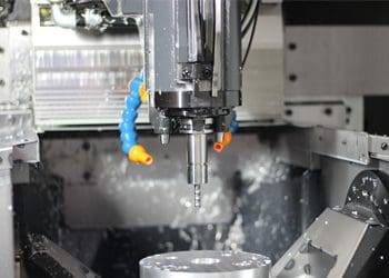
These parts are machined on a turn-mill center—a machine that can rotate the workpiece (like a lathe) and also move cutting tools in multiple axes (like a mill). This allows features such as threads, grooves, flats, holes, and contours to be machined in one clamping. Typical examples include shafts with cross holes, threaded fittings with wrench flats, and housings with internal and external geometries.
02Why Use Turn-Mill Instead of Separate Operations?
Tighter tolerances – No error from repositioning between machines.
Faster throughput – Eliminates setup time and work-in-progress handling.
Better surface finish – Single setup maintains consistent reference points.
Lower cost for complex parts – Reduces labor and fixture expenses.
A common case: a hydraulic valve spool requires a precise cylindrical body (turned) plus a drilled cross-hole and two milled flats. On separate machines, operators risk misalignment. On a turn-mill, all features are referenced from the same rotation axis, achieving ±0.01 mm positional accuracy.
03Key Design Guidelines for Turn-Mill Composite Parts
1. Minimize Tool Interference
Leave enough space between features for the live tool to reach. For example, when milling a flat near a shoulder, the tool holder’s diameter must clear the part. A rule of thumb: keep the distance from any milled feature to an adjacent diameter at least 1.5× the tool diameter.
2. Balance the Workpiece
Unbalanced parts cause vibration and poor surface finish. If your design has a heavy offset (e.g., a large flat on one side), add a counterweight or plan for lower spindle speeds. Many shops reduce RPM by 30–50% for unbalanced composite parts.
3. Use Standard Tool Sizes
Custom end mills or drills increase lead time and cost. Stick to common metric or imperial sizes (e.g., 3 mm, 6 mm, 10 mm drills; 6 mm, 10 mm, 12 mm end mills). For cross holes, specify diameters that match standard drill bits.
4. Specify Tolerances Clearly
Separate turned tolerances (e.g., diameter, roundness) from milled tolerances (e.g., position, flatness). Example: “Shaft diameter Ø25 h6; cross hole position ±0.05 mm relative to flat surface.” Avoid over-tolerancing non-critical areas.
5. Include Chamfers and Radii

Sharp internal corners are impossible to mill because tools are round. Add a radius at the bottom of any milled pocket (minimum 0.5 mm for small tools, 1 mm for tools >6 mm). For turned-milled transitions, a 0.2–0.5 mm chamfer helps deburring.
04Material Considerations
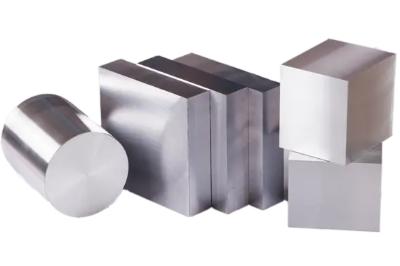
Aluminum (6061, 7075) – Excellent for turn-mill, good chip control.
Stainless steel (303, 304, 316) – Requires rigid setup and sharp carbide tools. Reduce cutting speed by 40% compared to aluminum.
Brass (C360) – Free-machining, ideal for small composite parts like fittings.
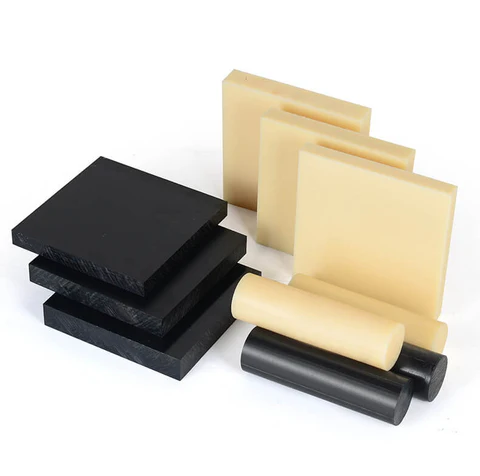
Plastics (PEEK, Delrin, Nylon) – Use sharp inserts and avoid high heat. Milling plastics often needs higher RPM and slower feed to prevent melting.
A real example: a medical device component made from 316L stainless steel had both a turned thread (M6×0.75) and four milled slots (2 mm wide). The shop used a turn-mill with through-tool coolant, running at 800 RPM for turning and 4,000 RPM for milling, achieving 0.02 mm tolerance on slot depth.
05Common Mistakes and How to Avoid Them
06How to Order Turn-Mill Composite Parts (Actionable Steps)
1. Review your design – Check for interference, balance, and standard tool sizes using the guidelines above.
2. Create a complete drawing – Include all turned and milled dimensions, tolerances, and surface finish requirements. Mark the reference surfaces for milling.
3. Select the material – Confirm machinability with your shop. For hard materials (e.g., Inconel, titanium), expect 2–3× longer cycle time.
4. Request a process review – Ask the machinist to verify setup and tool access. A good shop will simulate the program and suggest improvements.
5. Specify quantity and delivery – Turn-mill saves most on medium to high volumes (100–10,000 pcs). For prototypes, many shops still use separate machines if the part is simple.
07Conclusion
CNC turning and milling is useful for parts that combine round features with holes, slots, flats, or side machining. When the part is designed for the process, it can reduce setups, improve accuracy, and lower cost per part. The key is to avoid tool interference, keep the workpiece balanced, use standard tool sizes, and add relief features where the tool needs clearance.
Before finalizing the design, run a toolpath simulation or ask an experienced machinist for a DFM review. Take one existing part that requires both turning and milling, redesign it using the five guidelines above, and compare cycle time and setup cost with your current method. In many cases, the biggest savings come not from changing suppliers, but from making the part easier to machine. At YPMFG, turn-mill projects are also reviewed for tool access, fixturing, and machining sequence to reduce secondary operations and unnecessary cost.