Large thin-walled aluminum frame parts are extremely prone to deformation — especially when material removal exceeds 90% and thickness tolerance is as tight as 0 ~ -0.018 mm. Add a flatness requirement of ≤ 0.12 mm and a fine surface finish of Ra 1.6 μm, and conventional machining methods simply aren’t enough.
At YPMFG, we combine optimized process planning, stress control, and custom fixture design to ensure dimensional stability, surface integrity, and consistent batch quality, even for the most demanding precision applications.
1. Process Analysis
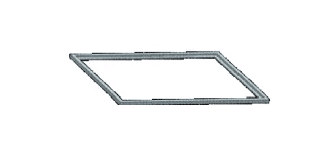
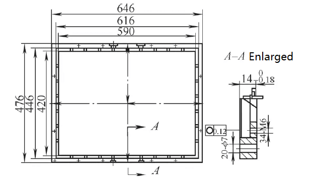
This pressure plate is a frame-shaped part, 650mm long, 480mm wide, with a total thickness of 140mm -0.018mm, and a minimum thickness of only 5mm, classifying it as a thin-walled part. There is a ring of holes on the inner cavity countersunk surface and on the large surface, and four semi-circular notches near the center line on the long side, as shown in Figure 2.
This pressure plate is designed as an integral frame made of aluminum alloy. As this part is in direct contact with the critical lens component, it requires high surface roughness, placing extremely high demands on the machining process. No scratches or marks are allowed on the surface. The key control points are a thickness tolerance of 0.018mm and a flatness ≤0.12mm.
Considering the small batch size and unsuitability for mold making, a 20mm thick aluminum plate was ultimately selected for direct cutting. The material removal rate during the machining process of this pressure plate part exceeds 90%, and the resulting machining stress will cause significant deformation. To ensure the finished product has a flatness of ≤0.12mm and a thickness of 140-0.018mm, the process route must consider the machining deformation of the parts. Artificial aging is required after rough machining to relieve machining stress.
Since aluminum alloys cannot be ground, to achieve the required surface roughness Ra=1.6μm, flatness 0.12mm, and thickness tolerance 0.018mm, a small-diameter aluminum alloy-specific tool can be used. Multiple passes with a small depth of cut can be used for finish milling, leaving a allowance for semi-finish milling. Flatness and thickness should be checked before final finish milling. The specific process route is: Purchase aluminum alloy sheet → Waterjet cutting → Rough milling (2.5mm allowance per side) → Artificial aging → Semi-finish milling (0.8mm allowance per side) → Flatness inspection → Finish milling → Milling grooves and drilling → Benchwork → Coordinate measuring machine inspection → Surface treatment.
2. Fixture Design
Vacuum adsorption devices are often used in the processing of thin-walled aluminum materials. However, the machining surface of this part is too small, and the space is insufficient to achieve a smooth seal. Therefore, it is necessary to consider using traditional fixtures to fix the part for precision machining.
(1) Reference Surface Fixture
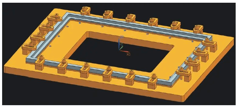
Because the part is made of aluminum alloy, using traditional clamping plates for fixing easily leaves indentations on the surface. Furthermore, changing the clamping plate during processing leads to discontinuous machining, resulting in tool marks that affect machining accuracy. In addition, an unreasonable clamping method during cutting can easily cause deformation of the workpiece itself, resulting in substandard machining accuracy. To find a clamping method that does not directly apply a clamping plate to the cutting surface and whose clamping force does not cause deformation of the workpiece, based on the above analysis, the fixture shown in Figure 3 was designed, allowing the workpiece to be cut in a basically free state for precision milling of the reference surface.
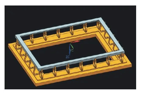
The structure of this fixture is shown in Figure 4: The base 4 is fixed to the worktable of the vertical machining center by a pressure plate. An elastic body 3 with rounded ends is fixed to the base 4 through bottom screw holes. The upper opening of the elastic body 3 clamps the pressure plate of part 1 using adjusting bolts 2. The clamping force of a single elastic body on part 1 is very small, and it will not cause product deformation during clamping. To prevent the workpiece from moving along the cutting direction during milling, multiple elastic clamping bodies are set along the contour of the part, which can meet the clamping and alignment requirements without causing clamping deformation.
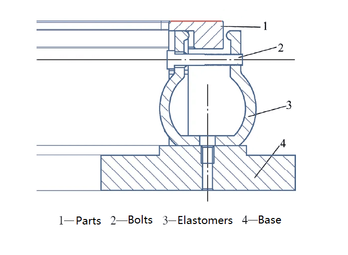
The working principle of this fixture is as follows: During machining, a sharp aluminum alloy special tool is used for cutting, with a small depth of cut. The X and Y directions are not completely restricted, so as not to affect the flatness. The Z direction is restricted by the top of the elastic clamping body, and cutting is basically performed in a free state, which can ensure flatness. This surface is used as the reference surface when machining the total thickness of the flipped surface.
(2) Non-datum surface fixture
The thickness tolerance range of the entire part is only 0.018mm. Besides ensuring the flatness of the datum surface during machining, the machining of the non-datum surface parallel to the datum surface is also crucial. In addition to meeting the accuracy requirements of the machine tool itself, improper clamping can cause part deformation, resulting in the inability to guarantee the thickness tolerance. Therefore, the fixture shown in Figure 5 was designed.
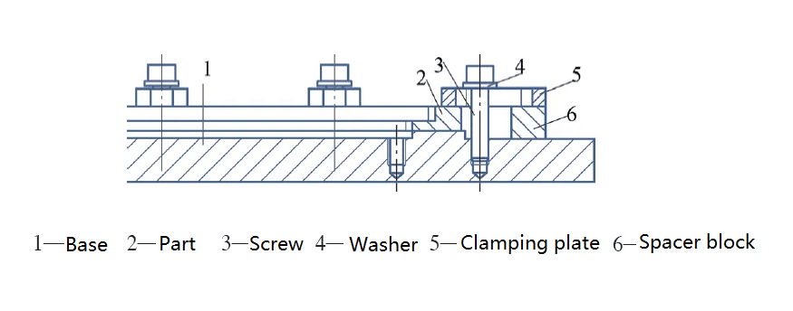
The structure of this fixture is shown in Figure 6: The fixture base plate 1 is fixed on the worktable, and the boss surface is precision milled to a flatness ≤0.01mm to serve as the support plane, and is kept clean. Part 2 is placed on the support surface, and multiple pressure points are set around part 2. Screws 3 are used to fix the pressure plate 5 to press part 2. It is important to note that the screws should not be tightened too much; it is best to use a torque wrench to control the force at each pressure point to ensure uniformity. When precision machining the inner countersunk surface and holes, the pressure plate 5 presses the outer ring. When precision machining the upper surface and holes, the pressure plate 5, pad 6, screws 3, and washers 4 are moved to the inner ring.
3. Process Validation
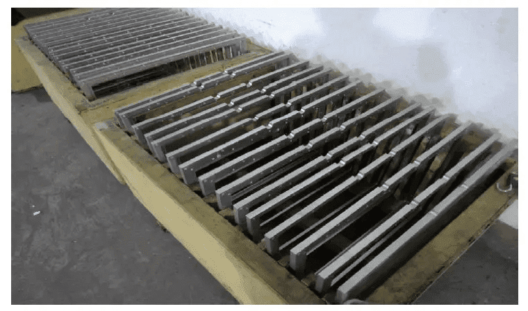
During actual finishing operations, the reference surface is machined using a precision milling fixture. The finished surface undergoes coordinate measuring machine inspection, with flatness ≤0.1mm. The reference surface is then clamped using a precision milling total thickness fixture. The clamping plate lightly presses the outer side while precision milling the inner cavity countersink to a thickness of 5mm. Subsequently, the clamping plate is moved to the inner side to lightly press the countersink area, precision milling the total thickness to 140 ± 0.018mm and all outer dimensions. To prevent surface damage, both the fixture base plate and clamping plate are fabricated from matching aluminum alloy. Positioning pins are strategically placed for limiting movement, enhancing setup efficiency for different parts within the same process. After machining, the part undergoes final CMM inspection, fully meeting drawing specifications. Following this process route and methodology in mass production, all delivered products met quality standards without any failures. The finished product is shown in Figure 7.
Conclusion
The machining of thin-walled aluminum alloy parts fully met the tolerances of 0–0.018 mm in the thickness direction and ≤0.12 mm in flatness, ensuring successful delivery to the customer. To meet the accuracy requirements of the drawings, special tooling was used to guarantee the accuracy of the datum surface, thus further ensuring the overall accuracy of the part. For special parts, we adopted flexible and diverse approaches in process and tooling design.