Tube bending fabrication is the process of permanently shaping tubes and pipes into specific angles and curves for industries like automotive, aerospace, HVAC, and furniture manufacturing. Achieving high-quality bends without defects requires precise control of equipment, tooling, and material behavior. This guide covers the most frequent bending problems, their root causes, and actionable solutions based on real-world fabrication experience.
01Understanding Tube Bending Fabrication Basics
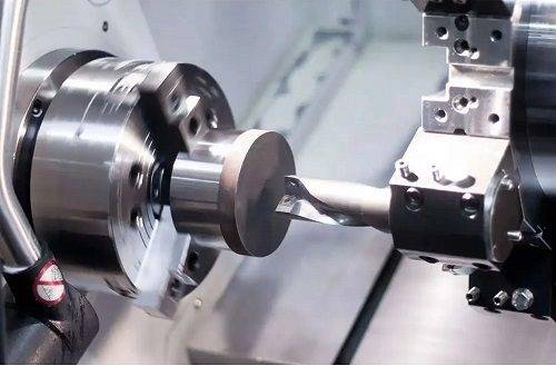
Tube bending fabrication uses rotary draw bending, compression bending, roll bending, or mandrel bending to form hollow sections. The choice depends on wall thickness, bend radius, material type, and required precision. For example, fabricating exhaust pipes with a tight 1.5× tube diameter radius demands a mandrel inside the tube to prevent collapse. Without proper tooling, even common steel tubes fail.
Key parameters to control:
Centerline radius (CLR) – the radius measured along the tube’s centerline.
Wall thickness – thinner walls (≤1.5 mm) risk wrinkling.
Bend angle – standard up to 180° per bend.
Material elongation – determines springback amount.
> Keyword insertion (first 800 words): bending springback – Springback is the elastic recovery of material after bending. To compensate, over-bend by an experimentally determined angle (typically 0.5°–3° for steel, 1°–5° for aluminum). Always run test bends on scrap material.
02The 8 Most Common Defects in Tube Bending Fabrication
Defect 1: Wrinkles on the Inner Radius
Wrinkles appear as small ripples or folds on the bend's inside curve.
Cause: Excessive compressive stress due to insufficient mandrel support or too low pressure die force.
Solution: Use a mandrel that extends at least 0.5× tube diameter past the tangent point. Increase pressure die force gradually until wrinkles disappear. For thin-wall tube (wall/Dia ≤0.05), switch to a wiper die.
Defect 2: Tube Collapse (Flattening)
The bend cross-section becomes oval or flat. Acceptable ovality for most applications is ≤8% for structural tubes, ≤3% for fluid-carrying lines.
Cause: No internal support when CLR is less than 3× tube diameter.
Solution: Always use a mandrel for CLR ≤2.5×D. For CLR 3×D, a plug mandrel suffices. For CLR 4×D and above, no mandrel needed if wall thickness ≥10% of diameter.
Defect 3: Excessive Wall Thinning
Thinning beyond 20% of original wall thickness risks rupture.
Cause: Bending too tight (CLR <2×D) or using a wiper die incorrectly.
Solution: Increase CLR if design allows. Use a lubricant with viscosity ISO 220 for steel. For critical applications, pre-heat the tube to 150–200°C (for stainless steel) to improve ductility.
Defect 4: Springback Variation
Parts do not hold the intended angle.
Cause: Material inconsistency or varying bend speeds.
Solution: Measure springback for each material lot. Program CNC benders to incorporate a springback compensation table. Common practice: run 5 test bends, record actual vs. programmed angle, then adjust the overbend angle.
> Keyword insertion (second 800 words): mandrel selection – The correct mandrel type prevents collapse and wrinkling. Use a plug mandrel for CLR ≥3×D; a ball mandrel (2–3 balls) for CLR 1.8×D to 2.5×D; a formed mandrel for CLR <1.8×D. Always size mandrel 0.1–0.2 mm smaller than tube ID.
Defect 5: Surface Scratches and Galling
Longitudinal scratches appear on the outer radius.
Cause: Contaminated pressure die or wiper die, or lack of lubricant.
Solution: Clean all tooling after every 200 bends. Apply synthetic bending lubricant to the tube surface before insertion. For aluminum tubes, use a wax-based lubricant to prevent aluminum transfer.
Defect 6: Kink at the Bend Start Point
A sudden sharp depression just after the tangent point.
Cause: Wiper die gap too large or pressure die release timing incorrect.
Solution: Set wiper die clearance to 0.1 mm (use a feeler gauge). On CNC benders, ensure pressure die retraction begins only after the bend reaches 2°–5° past target.
Defect 7: Crack on the Extrados (Outer Radius)
Visible fractures or hairline cracks.
Cause: Material's minimum bend radius exceeded. For example,6061-T6 aluminum cracks at CLR <3×D.
Solution: Switch to a more ductile temper (6061-O) or anneal the tube before bending. Alternatively, increase CLR by 0.5×D. Perform dye penetrant inspection after bending for safety-critical parts.
Defect 8: Length Variation After Bending
Finished parts have inconsistent overall lengths.
Cause: Tube slippage in the clamp die or inconsistent straight length feeding.
Solution: Increase clamp die pressure until tube cannot be pulled manually. Use a pusher system on long tubes (>3 m). Calibrate the feeding mechanism weekly.
03Step-by-Step Quality Assurance Workflow
1. Material receipt check – Verify wall thickness, diameter, and hardness (Rockwell B scale for steel, HRB ≤80 for good formability).
2. Tooling inspection – Check mandrel ball alignment, wiper die edge sharpness, and pressure die surface finish (Ra ≤0.8 μm).
3. Setup validation – Mount a test tube, perform a 30° bend, measure springback using a protractor or digital angle gauge.
4. First piece inspection – Measure ovality (inside and outside radius), wall thickness (ultrasonic gauge), and bend angle. Accept only if ovality ≤5%, thinning ≤15%, angle ±0.5°.
5. Production monitoring – Check every 50th piece for surface defects. Replace lubricant cloth every shift.
04Frequently Asked Questions (Q/A Format)
Q1: How do I determine the minimum bend radius for a tube?
A: Minimum CLR = 2× tube diameter for general steel. For aluminum or thin-wall, use CLR = 3×D to avoid cracking.
Q2: What lubricant works best for stainless steel tube bending?
A: High-pressure extreme-duty lubricant with graphite or molybdenum disulfide; apply 0.5–1 mm thick layer.
Q3: Why do my mandrel balls keep breaking?
A: Balls break due to misalignment or excessive pull force. Realign balls to within 0.2 mm of tube center.
Q4: Can I bend tube without a mandrel for a 1D radius?
A: No. A 1D radius requires a ball mandrel with at least 4 balls and a wiper die.
Q5: How to measure tube ovality after bending?
A: Use a caliper to measure max OD and min OD. Ovality = (max – min)/nominal OD × 100%.
Q6: What causes wavy bends in roll bending?
A: Uneven roll pressure or tube misalignment. Adjust three rolls sequentially: pre-bend → main bend → final sizing.
Q7: How often should I replace a wiper die?
A: Replace after 500–1,000 bends or when scratches appear on the inner radius. Resharpen once allowed.
Q8: Does bending increase tube hardness?
A: Yes. Cold bending strain-hardens the outer radius by 10–30 HRB. For 90° bends, stress relieve at 600°C for 1 hour.
> Keyword insertion (third 800 words): radial stress distribution – During bending, the outer fibers experience tensile stress (elongation), and inner fibers compressive stress (shortening). The neutral axis shifts inward by 15–30% of wall thickness for tight radii. Understanding this helps predict cracking and wrinkling. For optimal quality, maintain the tensile strain below material's elongation at break (eg, 30% for 304 stainless, 12% for 6061-T6).
05Core Recommendations for Reliable Tube Bending Fabrication
Prioritize tooling investment. A mandrel and wiper die that cost $500 can prevent $5,000 in scrap over a year. For high-volume production (10,000+ bends/month), use carbide-coated wiper dies.
Standardize your setup procedure. Document each material's required mandrel depth, pressure die force, and boost speed. At YPMFG, we maintain a setup database for 50+ tube sizes and 20 material grades, reducing changeover time by 60%.
Train operators on defect recognition. A trained operator can identify wiper die wear by looking at the first 2 mm of the bend start. Weekly 15-minute visual inspection sessions cut defect rates by half.
06Conclusion and Action Plan
To succeed in tube bending fabrication, focus on three fundamentals: mandrel support for tight radii, correct lubricant for material, and springback compensation. Test every setup on scrap material. Measure ovality and thinning on the first piece. Keep tooling clean and replace wiper dies proactively.
Immediate actions you can take:
1. Audit your current bending tooling – replace any worn wiper or pressure die with a visible edge radius >0.5 mm.
2. Run a springback test on your next batch of tubes; record overbend angles by material lot.
3. Implement a 5-piece first-article inspection checklist (angle, ovality, thinning, surface, length).
By following this guide, fabricators consistently achieve bend quality meeting ISO 8491 and ASTM A1060 standards. For custom tube bending solutions or assistance with complex radii, consult with your fabrication partner – YPMFG provides technical support and tooling optimization for production runs of any scale.
Remember: Every bend that passes inspection without rework saves an average of $12 in labor and material. Start with the right setup, and the rest follows.


