In the manufacturing industry, one inescapable issue is the existence of cumulative tolerances. These can manifest in two forms:
– Cumulative tolerances on individual parts
– Cumulative tolerances in assemblies.
The accumulation of tolerances can lead to machining difficulties, assembly challenges, or even cause what was originally designed as a clearance fit to result in interference. Many years ago, a design engineer failed to account for cumulative tolerances when dimensioning drawings. They specified tolerances for every length dimension on a part while also dimensioning the overall length with a tolerance. See the illustration below:
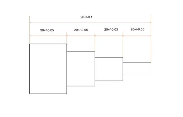
Figure 1 clearly shows dimensioning errors. First, the drawing specifies five dimensions, forming a closed loop. Under normal circumstances, dimensions within a closed loop should only be marked as reference dimensions without tolerances. Second, the cumulative tolerance of four +/-0.05 dimensions should be +/-0.2, yet the total length tolerance is only +/-0.1—clearly illogical. During machining, if the total length dimension is met, the tolerances for the individual segments must be tightened, conversely, if the individual segment dimensions are met, the total length requirement cannot be satisfied.
This is precisely the situation encountered by the supplier during machining. They consistently failed to meet tolerance requirements, resulting in a 50% defect rate. Eventually, through trial and error, they developed a method to bring all dimensions within tolerance. However, a surprising issue arose: after assembly, the part became impossible to fit together. This was an unexpected complication, likely caused by another mating part also experiencing tolerance accumulation or inconsistent tolerance values.
This case demonstrates that the impact of tolerance stack-up must be considered during initial design. It can lead to manufacturing difficulties or assembly failures.
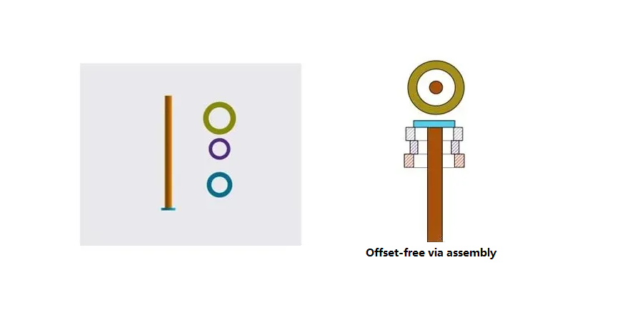
Here’s another example illustrating tolerance accumulation during assembly. In clearance fits, tolerance accumulation becomes particularly evident because assembly misalignment introduces additional tolerance stack-up. Consider the assembly of a piston rod and three rings shown below. Since this is a clearance fit, manual assembly may result in two scenarios depicted in Figure 2:
– All three rings tilting toward one side
– Or exhibiting random misalignment.
Once the three rings are assembled and secured by another component, they become immovable. When subsequently inserted into a circular sleeve, the rings may rub against the sleeve’s inner wall, ultimately compromising the product’s lifespan.
Notes:
-Multiple offset directions increase the overall outer diameter of the rings
-When offset occurs in one direction, the radius on the offset side becomes larger once the assembled piston rod dimensions are fixed.
This assembly offset typically cannot be specified on drawings but manifests during actual assembly. Consequently, it is easily overlooked yet causes significant issues.
Automated assembly eliminates this additional tolerance accumulation. In automated processes, the piston rod is first secured, followed by robotic gripping of components and precise centering during assembly, preventing offset. As shown in Figure 3, all three rings are centered, fixed, and then mated with the sleeve. This eliminates the accumulation of additional tolerances, meeting design requirements and delivering significantly superior performance compared to the assembly method shown in Figure 2.
Many believe automated assembly solely enhances production efficiency. This perspective is overly narrow. As demonstrated in the above case, automated assembly contributes to consistent product quality.
Regardless, cumulative tolerances always exist and cannot be eliminated. Adding a note to the drawing stating “No cumulative tolerances allowed” does not solve the problem. The correct approach is to account for cumulative tolerances and their consequences when dimensioning, thereby specifying acceptable tolerance dimensions.
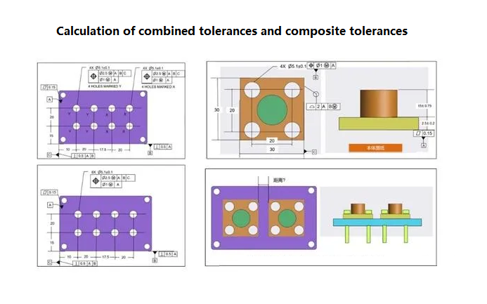
Mechanical design and GD&T geometric tolerancing provide methods for this. As shown in Figure 3, the distance from X to Y must be calculated: Method 1 has a cumulative tolerance of +/-0.15. Method 2 has a cumulative tolerance of +/-0.1. Method 3 has a cumulative tolerance of +/-0.05. If solely considering the magnitude of cumulative tolerance, Method 3 is clearly superior. However, when factoring in manufacturing costs, other annotation methods may be preferred.

In GD&T, combining tolerance and composite tolerance annotation methods can also reduce tolerance stackup. The first row of combined or composite tolerances typically specifies a more lenient requirement, economically meeting manufacturing cost demands. The second row can then impose tighter tolerances, particularly suited for feature groups—where two or more features (e.g., holes and shafts) share identical requirements and exhibit cumulative tolerance relationships. If the first row’s tolerances are excessively large, leading to unacceptable cumulative tolerances, the second row can be tightened. This approach satisfies both economic and functional requirements.
Of course, simultaneous requirements within GD&T also offer a solution. Applying simultaneous requirements to identical features can partially reduce tolerance accumulation. For example, in the assembly shown below, the blue part must be assembled with two bolts from the right diagram. Different annotation approaches are possible:
1. The top-left uses simultaneous requirements for hole groups X and Y, but groups X and Y are specified separately
2. The bottom-left corner uses eight holes as a simultaneous requirement.
Through dimensional chain calculations, the first dimensioning method causes interference during the assembly of two bolts due to cumulative tolerances resulting from assembly misalignment. The second method ensures smooth assembly between the two bolts. Due to space and text limitations, we cannot elaborate here on how combined tolerances, composite tolerances, and simultaneous requirements reduce tolerance accumulation.
In conclusion: Due to limitations in knowledge and experience, it may not be feasible at this stage to comprehensively list all hazards, causes, and solutions related to tolerance accumulation. However, we can identify and resolve these issues through practical application, thereby optimizing tolerances.
Tolerance design is an iterative refinement process, no single method can solve all problems. We should approach manufacturing issues with a level-headed attitude and resolve them using our capabilities. Of course, when proven methods exist—such as the tolerance design approaches mentioned in this article, we should adopt them to prevent problems before they occur.