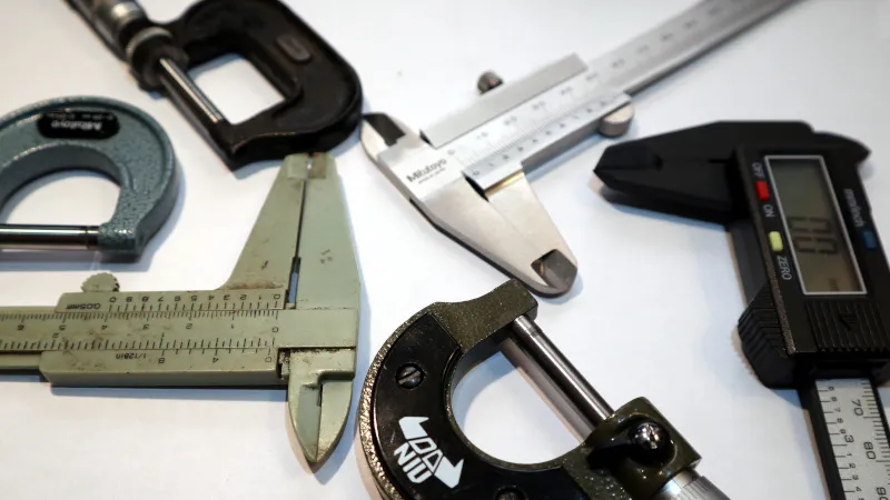
In manufacturing, circular components are far more common than flat ones. From small items like screws, nuts, and washers to larger components such as cylinders and bearings, nearly all rely on circular structures. As a key indicator of geometric precision, “roundness” directly impacts a part’s assembly performance and service life. This article will briefly introduce the definition of roundness, its tolerances, sources of error, measurement and evaluation methods, as well as common measurement tools, based on relevant standards (ISO/DIS 1101:2017, ISO 5459).
Table of Contents
What is Roundness?
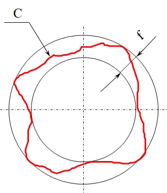
In the definition and representation of geometric form and position deviations per JIS B0621-1984, roundness is defined as the deviation from the geometric size of a perfect circle for a circular form. Its representation is documented as follows: When a circular form (C) is sandwiched between two concentric geometric circles, the roundness is expressed as the difference in radius (f) between the two concentric circles at the point where their separation is minimal. Roundness is specified in millimeters (mm) or micrometers (μm).
For rotating components, the pressing issue that often needs to be addressed is how to evaluate their true circularity. This brings us to the topic of “roundness tolerance.”
What is Roundness Tolerance and Error Sources?
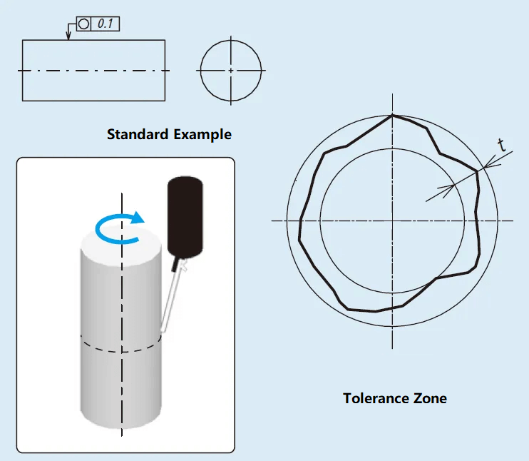
The roundness tolerance zone refers to the tolerance zone between two concentric circles on the same cross-section. As shown in the figure below, the extracted circumference must be confined within the tolerance zone between two coplanar concentric circles with a radius difference of t.
Why do roundness and cylindricity tolerances arise? Typically, the following reasons are involved:
- Poor roundness and cylindricity caused by the vibration of the machining equipment.
- Poor roundness and cylindricity caused by the deterioration of rotating components in machining equipment.
- Poor roundness and cylindricity caused by the poor shape of the center holes.
- Poor roundness and cylindricity during centerless grinding due to deformation from preceding processes.
- Workpiece distortion caused by improper fixtures or holding methods for ring-shaped components.
- Roundness defects caused by cutting tool wear, improper mounting, vibration, etc,.
- Deformation caused by heat treatment after finishing.
How to Measure and Evaluate Roundness?
There are numerous methods for evaluating roundness, each with its own characteristics and advantages. Typically, we select the appropriate method based on the specific requirements of the workpiece.
Simple measurement methods, such as:
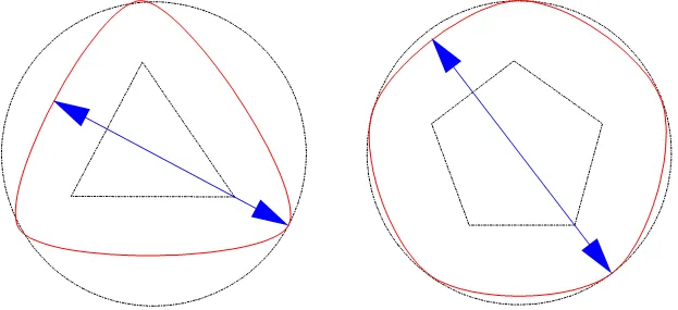
Diameter Method

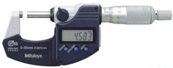
Directly read the diameter of the roundness using measuring tools such as micrometers.
This simple measurement method is extremely straightforward and easy to operate. However, when evaluating strain circles with non-circular shapes like triangles or pentagons, it is prone to misreading them as perfect circles.
Three-Point Method
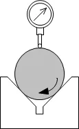
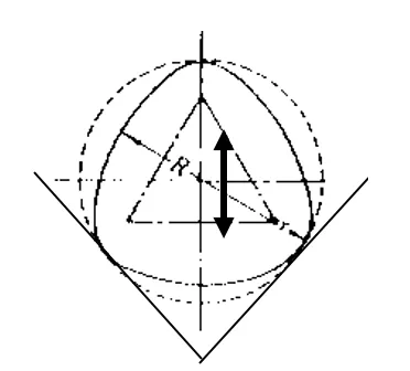
The three-point method can obtain roundness data using a V-block + micrometer/dial gauge + stand.
However, the tangents at the selected support points in the three-point method may differ, potentially leading to inaccurate measurements. The center of the reference cannot be determined, and vertical displacement occurring during the rotation of the measured object will introduce errors.
Measurement methods based on relevant standards, such as:
Radius Method
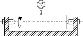
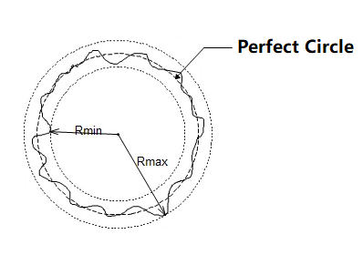
The radius method evaluates roundness by utilizing the difference between the maximum and minimum radius values obtained during one full rotation of the workpiece. As shown in the figure below, this evaluation method is also highly susceptible to the horizontal movement of the workpiece.
Center Method
The center method is comparatively more suitable for precision measurement requirements. Roundness inspection data relies on a reference circle. Different evaluation methods for the reference circle result in varying center positions, thereby affecting the axial position of the measured circular feature.
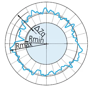
Least Squares Circle (LSC)
By fitting a circle to the measured profile, the method minimizes the sum of squares of deviations between the profile data and the fitted circle. The roundness value is then defined as the gap between the profile’s maximum deviation (peak-to-peak) from this circle.
ΔZq = Rmax – Rmin, where LSC denotes the sign of the roundness value.
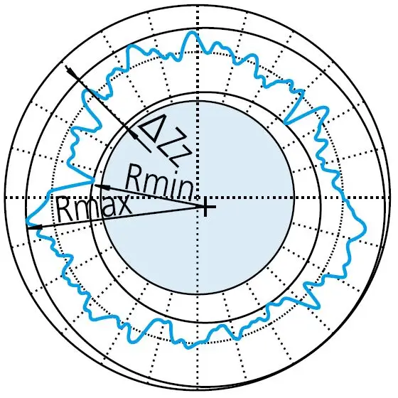
Minimum Zone Circle (MZC)
Enclose the measured profile by locating two concentric circles to minimize their radial difference. Define the roundness value as the radial gap between these two circles.
ΔZz = Rmax – Rmin, where MZC denotes the sign of the roundness value.
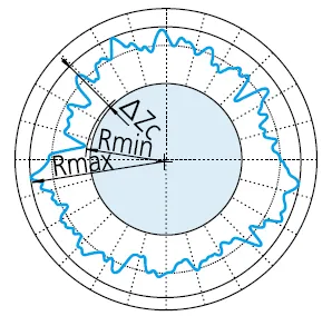
Minimum Enclosing Circle (MCC)
Creates the smallest circle that can encompass the measured contour. The roundness value is then defined as the maximum deviation between the contour and this circle, commonly used in evaluating shafts, rods, and similar components.
ΔZc = Rmax – Rmin, where MCC denotes the sign of the roundness value.
Maximum Inscribed Circle (MIC)
Create the largest circle that can enclose the measured profile. Then define the roundness value as the maximum deviation between the profile and this circle.
ΔZi = Rmax – Rmin, where MIC denotes the sign of the roundness value.
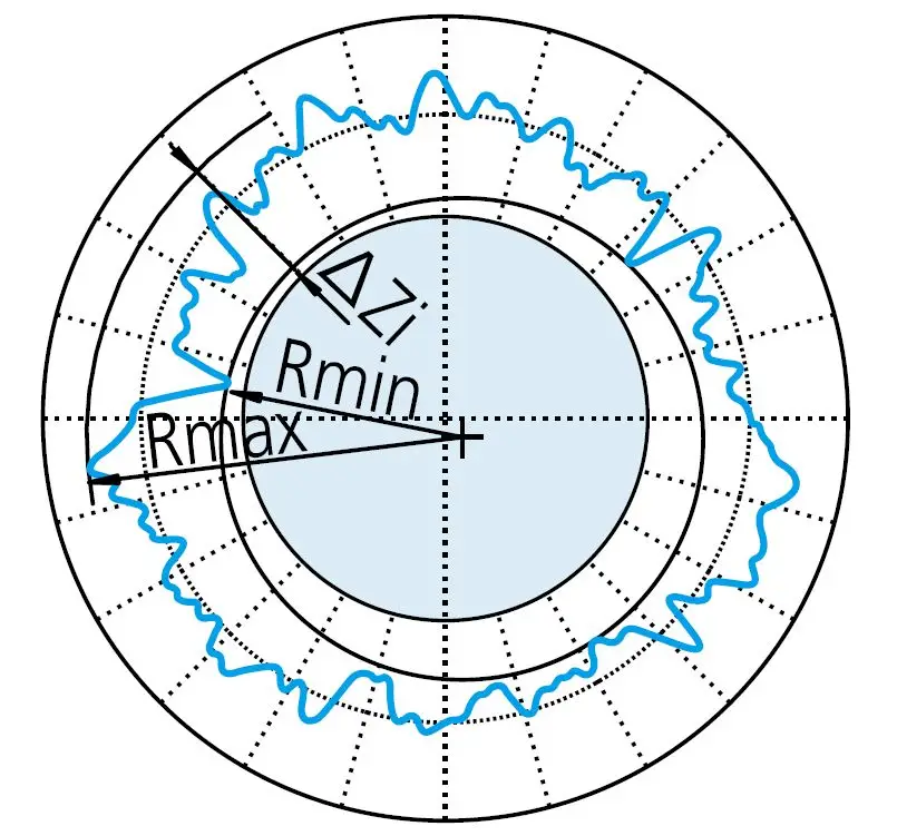
During the evaluation of roundness, filtering is typically applied to the obtained profile to reduce or eliminate the impact of unnecessary noise.
Effect of Filters on Measured Profiles
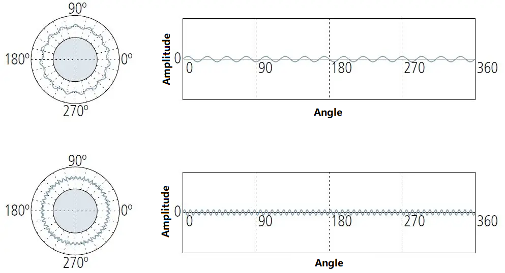
Depending on measurement requirements, different filtering methods are employed with varying cutoff values set. (UPR: Fluctuation per revolution) As shown in the figure below, the filter settings have distinct effects on the measured profile.
No filter:
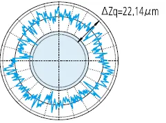
Low-pass filter:

Bandpass filter:

Analysis of Measurement Charts

1UPR Component
1UPR: Only one wave is retained after filtering.
The 1UPR component indicates the eccentricity of the workpiece relative to the rotational axis of the measuring instrument. The amplitude of the waveform depends on its horizontal adjustment.

2UPR Component
The 2UPR component may indicate:
① Insufficient horizontal adjustment of the measuring instrument.
② Circular runout caused by incorrect mounting of the workpiece on the machine tool forming its shape.
③ The workpiece’s shape is elliptical by design, such as in internal combustion engine pistons.

3~5 UPR components
Possible causes:
① Deformation caused by excessive tightening of the holding chuck on the measuring instrument.
② Relaxation deformation resulting from stress release during unloading from the fixed chuck of the machining tool.
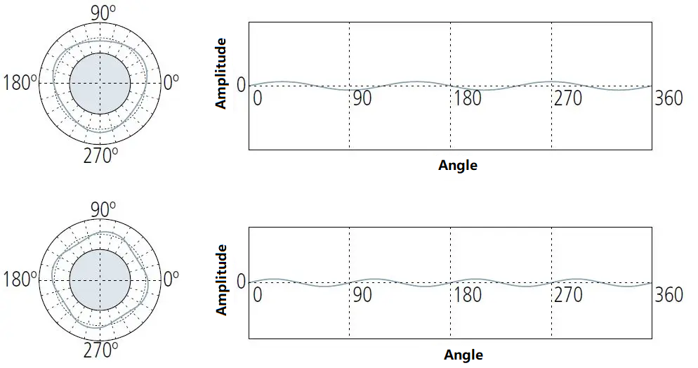
5~15 UPR components
Typically represents unbalanced factors in the machining process or during the production of workpieces.
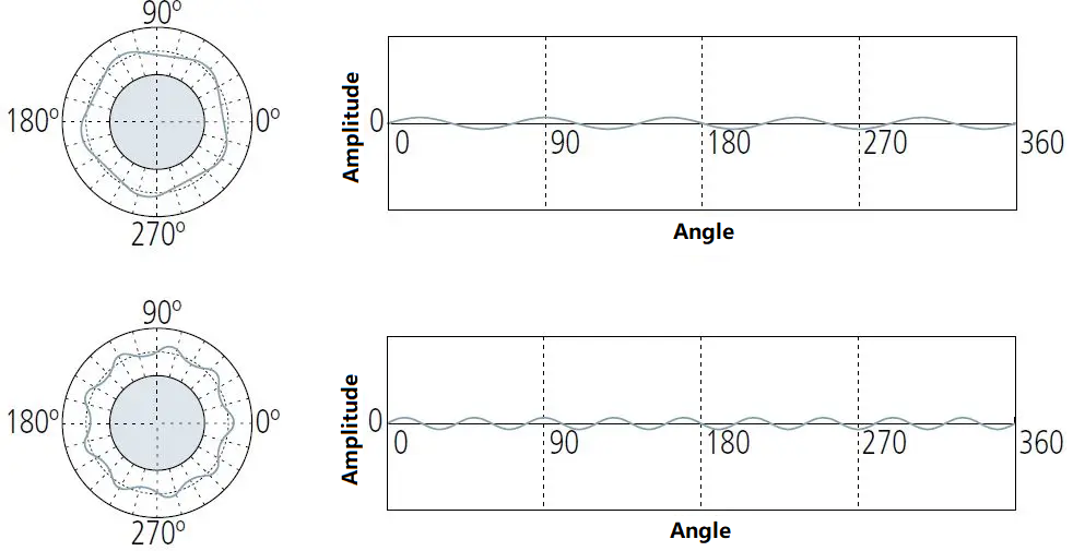
15 (or more) UPR components
15 (or more) UPR conditions are typically caused by inherent factors such as tool chatter, machine vibration, coolant delivery effects, and material inhomogeneity.
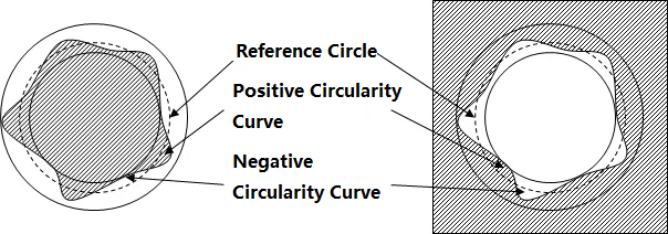
Key Parameters for Evaluating Roundness
| Parameters | Meaning |
| RONt | Roundness measurement value, representing the difference between the maximum value of the positive roundness curve and the minimum value of the negative roundness curve, or the sum of their absolute values. |
| RONp | Roundness curve peak height measurement value, representing the maximum value of the positive roundness curve. |
| RONv | Roundness measurement value, representing the absolute value of the minimum value of the negative roundness curve. |
| RONq | Root Mean Square (RMS) Roundness Measurement Value: Represents the square root mean square of the roundness curve. |
Common Measurement Tools and Instruments
Micrometer: Suitable for quick and easy inspection.
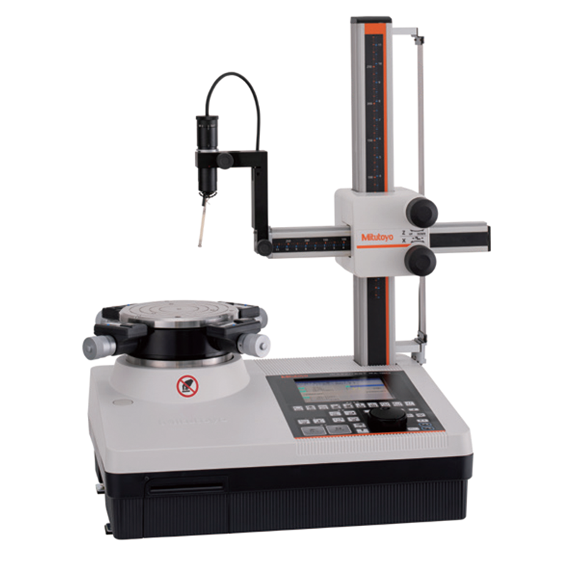
Roundness measuring instrument: High-precision evaluation of roundness and cylindricity.
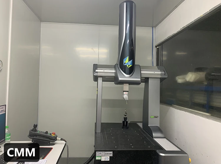
Coordinate measuring machine (CMM): Comprehensive inspection of dimensional and geometric tolerances.
Conclusion
Roundness is not only a critical indicator of geometric accuracy but also a reflection of machine performance, process stability, and material characteristics. Choosing the right measurement methods and tools, combined with proper data analysis, is essential to ensure the reliability and longevity of components.
At the same time, YPMFG has a complete testing process and advanced measuring instruments, ensuring strict compliance with international standards for roundness and related geometric tolerances. This guarantees machining precision and product reliability right from the start.

