Table of Contents
1. What is a Shaft?
A shaft is essentially any rotating component of a machine with a circular cross-section, used to transmit power from one part to another or from a power-generating device to a power-absorbing device. To transmit power, one end of the shaft is connected to the power source, while the other end is connected to the machine. Shafts may be either solid or hollow, depending on the application. Hollow shafts help reduce weight and offer certain advantages.
Shafts are among the most important elements used in machinery. They are employed to support rotating parts such as pulleys and gears, which are mounted on bearings within a rigid machine housing. The gears and pulleys located on the shaft assist in transmitting motion.
Many other rotating elements are also mounted on shafts using keys. Due to the reaction forces from the supported components and the torque generated during power transmission, shafts are subjected to both bending moments and torsional stresses.
Shafts always have a circular cross-section, which can be either hollow or solid. They can be classified as crankshafts, straight shafts, articulated shafts, or flexible shafts, but straight shafts are most commonly used for power transmission.
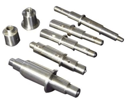
Shafts are usually designed as stepped cylindrical rods, so they have varying diameters along their length, even though shafts with constant diameters are easier to manufacture.
In a stepped shaft, the magnitude of stress varies along its length. Shafts with a uniform diameter are less suitable for disassembly, assembly, and maintenance. Moreover, such shafts complicate the secure mounting of components, especially bearings.
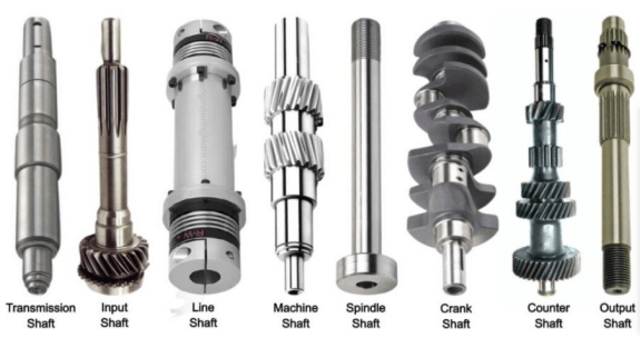
2. Types of Shafts
01. Drive Shaft
A drive shaft is a stepped shaft used to transmit power from one source to another machine that absorbs power. Motion is transmitted through the stepped sections of the shaft where gears, hubs, or pulleys are mounted. Examples include overhead shafts, line shafts, auxiliary shafts, and all factory shafts.
02. Machine Shaft
A machine shaft is located inside a component and is a part of the machine. For example, the crankshaft in an automobile engine is a machine shaft.
03. Axle Shaft
An axle shaft supports rotating elements, such as wheels. It can be installed in a housing with bearings, but the shaft itself is non-rotating. Axle shafts are mainly used in vehicles, such as the axles in cars.
04. Spindle
A spindle is the rotating part of a machine that holds a tool or workpiece. It is used for short shafts in machines, such as the spindle in a lathe.
3. Materials for Shafts
| Load Condition | Common Materials | Heat Treatment & Hardness | Characteristics |
|---|---|---|---|
| General Purpose | 35, 45, 50 High-Quality Carbon Steel | Quenching and tempering, 230–260 HBS | Low cost, balanced performance |
| Light Load or Secondary Shaft | Q255, Q275 | Normalizing or untreated | Economical choice |
| High Load Shaft | 40Cr | Quenching and tempering or hardening, 35–42 HRC | High strength, good toughness |
| High-Speed Heavy Load Shaft | 20Cr, 20CrMnTi, 38CrMoAlA, etc. | Carburizing or nitriding | Hard surface, tough core |
| Complex Structure Shaft | Ductile cast iron, high-strength cast iron | — | Good vibration damping, impact resistance |
| Precision Lead Screw | 45 Steel, T10, CrWMn, etc. | Quenching, 50–56 HRC | Ensures high precision and wear resistance |
Materials Used for Shafts Should Have the Following Characteristics:
- The material should have high strength.
- The material should have high wear resistance.
- The material should be suitable for heat treatment.
- The material should possess good mechanical properties.
- The material must have a low notch sensitivity factor.
4. Standard Dimensions of Shafts
Mechanical shafts can reach up to 25 mm in diameter, with a step increment of 0.5 mm.
Standard Dimensions of Drive Shafts – Step Increments:
- 25 mm to 60 mm – 5 mm step
- 60 mm to 100 mm – 10 mm step
- 110 mm to 140 mm – 15 mm step
- 140 mm to 500 mm – 20 mm step
The standard diameter for machine shafts can reach up to 25 mm, with a step increment of 5 mm. Standard shaft lengths are 5 m, 6 m, and 7 m, but typically, shafts are selected in lengths of 1 m to 2 m.
5. Shaft Loading and Design Calculations
The stresses generated in a shaft include:
- Shear stress caused by torque transmission (resulting from torsional load).
- Bending stress caused by forces acting on mechanical components (such as pulleys and gears) as well as the shaft’s own weight, which can be compressive or tensile in nature.
- Combined stress resulting from both bending and torsional loads.
Maximum Allowable Design Stress:
Maximum Allowable Shear Stress:
- For shafts with keyways: 56,000 kN/m²
- For shafts without keyways: 42,000 kN/m²
Maximum Allowable Bending Stress:
- For shafts with keyways: 112,000 kN/m²
- For shafts without keyways: 84,000 kN/m²
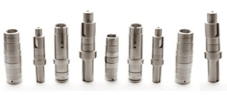
6. Shaft Manufacturing
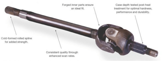
Shafts are manufactured using the hot rolling process. Compared to hot rolling, cold-rolled shafts have higher strength, but cold rolling introduces high residual stress, which can cause deformation during machining. Forging is used for manufacturing shafts with larger diameters.
After rolling, the shaft undergoes end machining. One end of the shaft is mounted on an inspection setup, while the other end is supported by the turret of a lathe. For precision machining, the cutting tool is fixed on the tool post, and when powered on, the chuck rotates the shaft.
A micrometer is used to check the shaft’s concentricity before machining, and various operations such as turning, facing, grooving, and taper turning are performed depending on its application. Large batch production and CNC machining are most suitable for the final machining process. Shafts can also be processed on CNC double-ended machines, where the shaft is clamped between a rotating tool and a fixture.
To achieve proper concentricity and roundness, the rotating tool must be aligned relative to the shaft’s centerline. Drive shafts and motors are commonly manufactured using this process.
7. Shaft Power Transmission
Shafts are used for power transmission, and the formula for calculating transmitted power is: P = 2πnT/ 60
Where:
- P = transmitted power (W)
- n= rotational speed (RPM)
- T = torque (Nm)
Typical shaft speeds for various applications:
- Mechanical: 100–200 RPM
- Woodworking machinery: 250–700 RPM
- Textile industry: 300–800 RPM
- Light machinery workshop: 150–300 RPM
- Auxiliary shafts: 200–600 RPM
8. Shaft Design
Shafts can be designed based on different loading conditions using two main approaches:
01. Strength-Based Shaft Design
Drive shafts are typically subjected to bending moments, torque, axial tension, or their combination. Usually, shafts experience combined torsional and bending stresses.
Tensile stress on a bearing: Tensile stress = P/A. Where A = (π/4) x D², D is the shaft diameter (in mm).
Bending moment on a bearing: Bending stress = (Mb x Y) / I. Where Mb = bending moment, Y = D/2, where D is the diameter, I = moment of inertia = (π x D²) / 64.
Torsionally on a bearing: Torsion stress = Mt x R/J. Where Mt = torsional moment, R = D/2, where D is the diameter, J = polar moment of inertia = (π x D²) / 32.
02. Stiffness-Based Shaft Design
{Mt/J} = {(G x ө)/ L}. Where, Mt = torque in N (mm), J = polar moment of inertia = (π x D4)/32, D = shaft diameter (mm), ө = torsion angle, G = stiffness modulus (design N/mm2).
Where:
- (M_t) = torque (N·mm)
- (J) = polar moment of inertia = (πxD4)/32
- (D) = shaft diameter (mm)
- (ө) = angle of twist
- (G) = shear modulus (N/mm²)
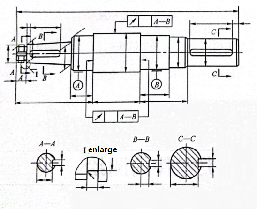
Representation of Views
- Shafts are mainly rotational parts, typically machined on lathes and grinders. A basic view is used with the shaft axis horizontal and the smaller end on the right for easier reference during machining.
- Single keyways on shafts should be drawn fully in the front view.
- Features such as holes and keyways are usually shown in sectional or partial views. Sectional views clearly convey the structure and allow dimensioning of tolerances.
- Small features like relief grooves or fillets are shown in enlarged partial views.
Dimensioning
- The primary reference in the axial direction is the main mounting end face (shaft shoulder). The ends of the shaft are usually measurement references, and the shaft axis serves as the radial reference.
- Main dimensions are noted first, multi-step lengths are dimensioned according to turning sequence. Local features are usually positioned relative to nearby shaft shoulders.
- To maintain clarity, inner and outer dimensions on sectional views should be dimensioned separately. Dimensions for different operations (turning, milling, drilling) should also be separated.
- Features such as chamfers, relief grooves, keyways, center holes, etc., should be dimensioned according to relevant technical standards.
Technical Requirements for Shafts
1. Dimensional Accuracy
- Main shaft journal diameters: IT6–IT9, precision shafts: IT5.
- Step lengths on stepped shafts: tolerances based on use or assembly dimension chains.
2. Geometric Accuracy
- Shafts are usually supported on bearings by two journals, which act as assembly references.
- Geometric accuracy of support journals (roundness, cylindricity) must be controlled.
- For ordinary shafts, geometric tolerances are usually within the diameter tolerance, for higher precision, additional shape tolerances are specified.
3. Positional Accuracy
- Concentricity of mating journals relative to support journals is a common requirement.
- Radial runout is commonly used to indicate this.
- Ordinary shafts: radial runout 0.01–0.03 mm, high-precision shafts: 0.001–0.005 mm.
- Axial alignment (perpendicularity of end faces to axis) is also considered.
4. Surface Roughness
- Support journals: Ra 0.16–0.63 µm
- Mating journals: Ra 0.63–2.5 µm
- For standard components, reference tables and technical standards are available.
9. Advantages and Disadvantages of Shafts
Advantages of Shafts:
- They are less likely to seize.
- Require less maintenance compared to chain systems.
- High torsional strength.
- High polar moment of inertia.
- Very robust and unlikely to fail.
- Hollow shafts use less material due to their hollow structure.
- For the same torque transmission, hollow shafts are lighter than solid shafts.
- High rotational radius.
Disadvantages of Shafts:
- Power loss due to loose coupling.
- Vibrations during rotation.
- Continuous noise generation.
- Higher manufacturing and maintenance costs.
- Manufacturing is challenging.
- Speed changes are not easy.
- Longer downtime due to mechanical issues.
- Oil dripping from overhead shafts.
- Using elastic couplings (e.g., leaf spring couplings) can cause speed loss between shafts.
- Shaft failure requires significant time for repairs.
A well-designed shaft not only affects the stability and lifespan of the transmission system but also directly determines the operating efficiency and maintenance cost of the entire machine.
From material selection, stress analysis, and precision control to manufacturing processes, every step requires a combination of professional experience and rigorous engineering practice.
If you are looking for a reliable partner for shaft component manufacturing, YPMFG Machining offers advanced CNC machining equipment and a complete quality management system, providing high-precision drive shafts, spindles, crankshafts, and customized non-standard shafts for various industries. Contact Us Now!