In today’s rapidly evolving industrial landscape, CNC machining has emerged as one of the most critical technologies in modern manufacturing. From precision aerospace blades and automotive structural components to electronic enclosures and connectors, high-precision, high-efficiency CNC machine tools are indispensable.
CNC machine tools not only enhance machining accuracy and consistency but also make the production of complex geometric parts more reliable and controllable.
Table of Contents
1. What is a CNC Machine?
A CNC machine (Computer Numerical Control Machine) is an automated machining device that uses computer programs to control the relative motion between cutting tools and workpieces. It can perform various machining tasks such as turning, milling, drilling, and cutting, and can manufacture complex parts with extremely high repeatability and precision.
Core advantages of CNC include:
- Exceptional dimensional accuracy and stability
- Capability to achieve intricate geometric features
- Suitability for both mass production and small-batch customization
- Reduced human error and enhanced consistency

2. How Does a CNC Machine Work?
The essence of CNC machining is the process of transforming designs into physical parts.
The complete workflow includes:
1. Generating G-Code Programs
Creating toolpaths from CAD models using CAM software.
2. Inputting Programs to the Control System
Loading programs via USB, network, or directly on the machine tool.
3. System Parsing G-Code
The CNC controller (MCU) interprets instructions within the code, such as feed rates, tool paths, and spindle speeds.
4. Actuating the System
Servo motors drive the X/Y/Z axes to execute cutting operations.
Correcting Errors via Feedback
Encoders and sensors continuously monitor position in real-time to maintain precision.
This closed-loop control mechanism enables CNC machines to operate stably with micron-level accuracy.
3. Structural Framework of a CNC Machine
CNC machine tools consist of the main body, numerical control unit, drive system, auxiliary devices, programming equipment, and other ancillary components.
(1) Main Machine: The main machine serves as the core component of CNC machine tools, encompassing mechanical parts such as the bed, column, spindle, and feed mechanism. It primarily performs various cutting operations.
(2) CNC Unit: The CNC unit is the core of the machine tool, comprising hardware (printed circuit boards, CRT displays, keyboards, paper tape readers, etc.) and corresponding software. It inputs digitized machining programs, stores input information, performs data conversion and interpolation calculations, and implements various control functions.
(3) Drive System: The drive system serves as the actuator for the machine tool’s executive components, including the spindle drive unit, feed unit spindle motor, and feed motors. Under the control of the CNC unit, it drives the spindle and feed mechanisms through electrical or electro-hydraulic servo systems. When multiple feeds are coordinated, it enables machining operations such as positioning, linear paths, planar curves, and spatial curves.
(4) Auxiliary Devices: These are essential supporting components for CNC machine tools, ensuring their operation through functions like cooling, chip removal, lubrication, lighting, and monitoring. Auxiliary devices include hydraulic and pneumatic systems, chip removal systems, indexing tables, CNC rotary tables, CNC indexing heads, as well as tooling and monitoring/inspection equipment.
(5) Programming and Other Peripheral Equipment: These enable off-machine programming and storage of part programs.
4. Key Components of CNC Motion Control
Motors and Drives
At the heart of CNC motion control are motors and drives. Motors (typically servo or stepper motors) convert electrical signals into mechanical motion. On the other hand, drives regulate the power supplied to the motor, influencing the machine’s speed, torque, and positioning accuracy.
CNC Controllers
The CNC controller serves as the system’s brain. It interprets CNC code and sends commands to motors, directing the machine’s precise movements. Advanced controllers offer features like multi-axis control and real-time feedback to enhance accuracy.
Ball Screws
Ball screws play a crucial role in converting rotational motion into linear motion. The helical arrangement of ball bearings within the screw enables smooth, precise movement along the axis, contributing to the overall accuracy of CNC machine tools.
Linear Guides
Linear guides direct machine components along specific paths. These guides ensure stability and precision by minimizing friction and backlash during motion. Common types include linear rails and bearings, facilitating smooth axial movement.
Encoders
Encoders provide real-time feedback on the position of machine components. This feedback is essential for CNC controllers to adjust and correct any deviations from the programmed path, ensuring the machine maintains the required precision level during operation.
Control Software
Control software serves as the interface between the operator and the CNC machine tool. It enables programming of machining operations, specifying tool paths, speeds, and depths. Intuitive and user-friendly software facilitates efficient CNC motion control.
Power Supply
A stable and reliable power supply is vital for consistent, precise motion control. Power fluctuations or interruptions can cause errors and interruptions during machining. A high-quality power supply ensures smooth, uninterrupted operation.
Emergency Stop System
Safety is paramount in CNC machining. The emergency stop system provides a quick and effective method to halt machine operation in unforeseen situations, preventing potential damage to the machine or workpiece.
Frame and Guideways
The structural components of the machine (including the frame and guideways) contribute to the overall stability and rigidity of the system. A robust frame and carefully designed guideways minimize vibration and deflection, ensuring precise motion control.
Tools and Workholding Fixtures
While cutting tools and workholding solutions are not direct components of the motion control system, their selection impacts overall performance. Proper tools and workholding fixtures contribute to the accuracy and stability of the machining process.
5. Classification of CNC Machines
The most critical aspect of CNC machine operation involves translating process analysis into machining programs recognizable by the CNC system. The CNC system serves as both the defining feature distinguishing CNC machines from conventional ones and the focal point of industry development. With diverse brands and specifications, CNC machines are categorized in several ways, primarily through the following four classifications.
1. Classification by Process Application
Based on process application, CNC machine tools fall into four categories: metal cutting, metal forming, special processing, and measuring/plotting.
Metal cutting refers to CNC machine tools employing various cutting processes such as turning, milling, reaming, drilling, grinding, and planing.
Metal forming machines employ forming processes like extrusion, stamping, pressing, and drawing. Common examples include CNC presses, CNC bending machines, CNC pipe bending machines, and CNC spinning machines.
Special-purpose machines primarily include CNC wire EDM machines, CNC die-sinking EDM machines, CNC flame cutting machines, and CNC laser processing machines.
Measurement and plotting machines primarily include coordinate measuring machines, CNC tool setters, and CNC plotters.

Among metal-cutting CNC machines, machining centers represent a crucial category. Capable of automatic tool changing, they enable multi-process machining of workpieces with a single setup. Machining centers can be classified by machining processes and the number of controlled axes. They can also be categorized based on the relative position of the spindle and worktable, such as horizontal machining centers and vertical machining centers. Machining centers are primarily suited for processing complex-shaped workpieces with multiple processes and high precision requirements, such as: box-type workpieces, complex curved surface workpieces, irregularly shaped parts, and disc, sleeve, and plate-type workpieces. Box-type workpieces typically require multi-station hole patterns and flat surface machining with high positioning accuracy. On a machining center, over half of the machining operations achievable on conventional machines can be completed in a single setup. Furthermore, machining centers enable specialized processes like surface hardening of metal surfaces by installing a frequency-modulated EDM power supply on the spindle.
2. Classification by Motion Mode
CNC machine tools can be categorized into three types based on tool motion mode: point-to-point control CNC machine tools, point-to-point linear control CNC machine tools, and contour control CNC machine tools.
The tool motion modes correspondingly fall into three categories: the first type only specifies the start and end points without defining the process, the second type plans the path and speed, controlling the process in a single direction but only following a predetermined route. The third type controls the tool’s movement path in two or more directions according to machining requirements, dynamically adjusting the path and feed rate. In essence, point-to-point control ensures precise positioning of the tool or worktable between two points. Linear point-to-point control builds upon this by controlling an additional coordinate axis to guide tool movement at a predetermined speed and trajectory. Contour control enables continuous regulation of displacement and speed across two or more motion axes.
Point-to-point control is commonly employed on CNC machines for hole drilling and straight-line milling operations. Machines featuring point-to-point control include CNC drilling machines, CNC milling machines, CNC punching machines, and CNC boring machines.
During movement, point-to-point linear control CNC machines enable cutting at a specified feed rate, typically limited to processing rectangular or stepped parts. Currently, CNC machines relying solely on point-to-point or point-to-point linear control are uncommon. Except for specialized control systems, modern computer numerical control (CNC) units incorporate contour control functionality.
Machine tools employing contour control primarily include CNC lathes, CNC milling machines, CNC wire-cutting machines, and machining centers. Their corresponding CNC devices are termed contour control CNC systems. Presently, all control functions of computer numerical control devices are implemented via software, meaning adding contour control capabilities does not incur additional costs.
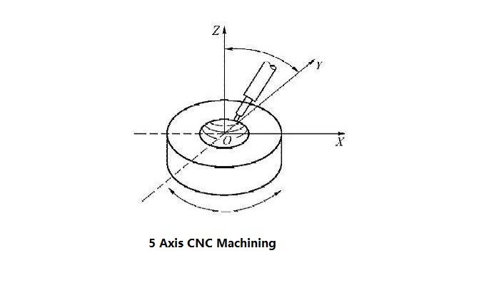
3. Classification by Number of Interconnected Coordinate Axes
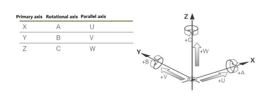
The coordinate axes controlled by CNC machine tools primarily include three linear axes (X, Y, Z) and rotational axes (A, B, C) that rotate around these linear axes. For CNC machine tools, a higher number of interconnected axes translates to greater degrees of freedom, enhanced machining capabilities, and the ability to process more complex parts. Therefore, to meet increasingly complex machining demands, the number of interpolated axes has continuously increased with the development of CNC machine tools. Currently, five-axis interpolation is the predominant configuration. Theoretically, five-axis interpolation can machine any non-closed shape. However, due to tool, tool holder, and fixture interference issues, certain shapes, such as impellers, require specialized tools.
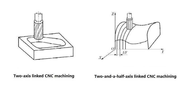
The minimum number of axes in CNC machine tools is two-axis linkage, primarily used for machining rotary surfaces on CNC lathes or curved cylindrical surfaces on CNC milling machines. Two-and-a-half-axis linkage is mainly employed for controlling machine tools with three or more axes, where two axes can be linked while the third axis performs periodic feed movements. Since it does not participate in full-time machine control, it is termed “two-and-a-half-axis linkage.”
Three-axis linkage comes in two types: the common three linear coordinate axes linkage, frequently used in CNC milling machines and machining centers and a type that, in addition to two linear axes, simultaneously controls a rotary axis rotating around one of the linear axes. For example, a turning machining center requires simultaneous control of the longitudinal (Z-axis), transverse (X-axis) linear axes, and the spindle (C-axis) rotating around the Z-axis. Three-axis CNC machines typically feature three linear axes working together, capable of machining only one surface at a time. They are suitable for processing disc-shaped parts but struggle with drilling holes or grooves on multiple machined surfaces.
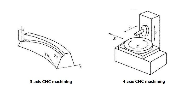
Four-axis CNC machines incorporate an additional rotary coordinate axis beyond the three-axis linkage, [SYT8] enabling unobstructed low-speed rotation in the horizontal plane. This configuration is ideal for machining box-type components. Most CNC machines also permit workpiece rotation, allowing such equipment to function as both milling machines and lathes. They are well-suited for drilling holes on the sides of parts or on the curved surfaces of cylindrical objects. Four-axis linkage significantly accelerates the machining process while maintaining high precision.
Five-axis machining is now commonly employed. Beyond the X/Y/Z linear axes, it simultaneously controls any two of the A, B, and C axes, enabling tool positioning in any spatial orientation. Five-axis CNC machine tools represent high-tech, high-precision equipment specialized for machining complex curved surfaces. These systems exert significant influence across industries including aerospace, precision instruments, and high-precision medical equipment. Five-axis CNC systems are employed to machine critical components such as impellers, blades, marine propellers, heavy-duty generator rotors, turbine rotors, and large diesel engine crankshafts.
4. Classification by Control Method
CNC machine tools employ three control methods: open-loop control, semi-closed-loop control, and closed-loop control. The term “loop” here refers to the feedback-inclusive closed-loop circuit illustrated in Figure 2 (Working Principle of CNC Machine Tools).
An open-loop control system refers to a control system without feedback devices.
A semi-closed-loop control system builds upon the open-loop system by incorporating angular displacement detection devices within the servo mechanism. These devices indirectly measure the displacement of moving components and feed this information back to the CNC unit.
A closed-loop control system directly installs linear position detection devices on the moving components of the machine tool.
In summary, the distinctions lie in the absence of feedback devices, the use of indirect feedback devices, and the implementation of direct feedback devices. Since the precision of open-loop feed servo systems in CNC machine tools cannot adequately meet the demands of CNC machining, the fundamental approach to ensuring accuracy is adopting closed-loop control. Closed-loop control systems enable direct measurement of the CNC machine tool’s worktable displacement and implement feedback control. By incorporating the CNC machine tool itself within the position control loop, errors caused by the mechanical system can be eliminated through feedback control. In open-loop control systems, information flow is unidirectional, meaning errors during machining will affect the precision of the workpiece. Therefore, open-loop control systems are only suitable for small and medium-sized CNC machine tools with lower machining precision requirements.
The servo mechanism in a semi-closed-loop control system achieves superior precision, speed, and dynamic characteristics compared to open-loop servo mechanisms. It is primarily applied in most small and medium-sized CNC machine tools, such as CNC lathes and CNC milling machines.
Within closed-loop control systems, the friction characteristics, stiffness, and backlash of many mechanical transmission links exhibit nonlinear behavior. This leads to system instability, making the design, installation, and debugging of closed-loop systems highly challenging. Currently, this system is primarily employed in machine tools requiring extremely high precision in production processes, such as boring machines, super-precision lathes, super-precision grinding machines, and certain large-scale CNC machining equipment.
5. Materials & Applications
CNC machining supports a wide range of materials:
Metals
- Aluminum 6061 / 7075
- Stainless steel 304 / 316 / 17-4
- Titanium Ti-6Al-4V
- Tool steels and alloy steels
Non-Metals
- POM/Delrin
- ABS, Nylon
- Composites
- Carbon fiber laminates
Industries Using CNC
- Aerospace: turbine blades, chassis
- Automotive: housings, engine components
- Medical: surgical tools, orthopedic implants
- Electronics: enclosures, heat sinks
- Robotics: precision gears, joints
6. Operation, Safety & Workflow
Typical CNC Workflow:
- Prepare CAD/CAM files
- Set workholding
- Load tools and set offsets
- Dry run simulation
- Machining cycles
- Inspection
Safety Practices:
- Proper grounding
- Enclosure closed during operation
- Use of PPE
- Regular coolant handling
- Emergency stop training
7. Maintenance & Troubleshooting
- Routine Maintenance Checklist
- Check spindle runout
- Inspect guideways and ball screws
- Replace cutting fluid regularly
- Clean chip conveyors
- Verify encoder alignment
- Check backlash values
| Issue | Cause | Resolution |
| Vibration marks | Loose fixturing | Re-tighten setup |
| Overheating | Coolant failure | Check pumps/filters |
| Dimensional drift | Thermal expansion | Warm-up cycles |
| Backlash | Worn ball screws | Compensation or replacement |
8. Upgrading CNC Machine Parts
Upgrading machine components can significantly improve performance without full replacement.
When to Upgrade:
- Reduced accuracy
- Increased cycle time
- Wear in motion systems
- Outdated controller
- Need for multi-axis capabilities
Common Upgrades:
- Servo motors
- Linear guideways
- Ball screws
- Spindle units
9. Conclusion
CNC machine tools are among the most critical tools in modern manufacturing. Understanding their structure, components, control methods, and maintenance practices enables businesses to maximize production efficiency, enhance machining quality, and extend machine tool lifespan.
Through continuous improvement and intelligent upgrades, CNC machining will continue driving industrial manufacturing toward higher levels.
If you’re seeking high-precision CNC machining services, we offer:
- Custom part machining
- Support for diverse materials
- Rapid turnaround with stringent quality control
- Upload your CAD files today to get an instant quote.