Hole is an important surface on box, bracket, sleeve, ring and disk parts, and is also a frequently encountered surface in machining. In the case of the same machining accuracy and surface roughness requirements, machining holes is more difficult than machining cylindrical surfaces, low productivity and high cost.
Low productivity, high cost is because:
1) Hole machining tool size is determined by the size of the hole being machined, subject to the limitations of the size of the rigidity of people with low incomes, easy to produce bending deformation and vibration.
2) Hole machining with a fixed-size tool, hole machining is often directly dependent on the size of the corresponding size of the tool. The tool manufacturing errors and wear will have a direct impact on the hole machining accuracy.
3) Machining of holes, the cutting zone in the interior of the workpiece, chip removal and heat dissipation conditions. Poor machining accuracy and surface quality are not easy to control.
Hole processing methods include drilling, reaming, reaming, boring, drawing, grinding and hole finishing. The following is a detailed introduction to several hole machining processes, cracking the hole machining problems.
Table of Contents
Drilling and Reaming
Drilling
Drilling is the first process of drilling holes in solid material, and the diameter of drilled holes is generally less than 80mm. There are two ways of drilling: one is rotating the drill, the other is rotating the workpiece.
The error generated by the above two drilling methods is not the same, in the drill rotating drilling method, due to the cutting edge asymmetry and rigidity of the drill bit is not enough to make the drill bit deflection, the centerline of the processed holes will be skewed or not straight, but the diameter of the hole is basically unchanged, and in the workpiece rotating drilling method is the opposite, the drilling bit deflection caused by the diameter of the hole will be changed, while the centerline of the hole is still straight.
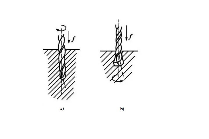
a) Drill rotation b) Workpiece rotation
Commonly used drilling tools: twist drills, center drills, deep hole drills, etc., of which the most commonly used is the twist drill, whose diameter specifications for the φ 0.1 ~ 80 mm. standard twist drill structure, the shank is the clamping part of the drill and used to transmit torque, drill shank has a straight shank and taper shank two kinds of the former is used for small-diameter drills, and the latter is used for large-diameter drills.
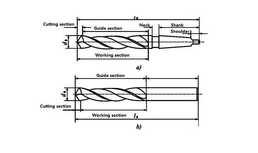
a) Taper shank b) Straight shank
Due to the structural limitations, the bending stiffness and torsional stiffness of the drill bit are low, coupled with poor centering, the accuracy of drilling and processing is low, generally only up to IT13 ~ IT11, the surface roughness is also larger, Ra is generally 50 ~ 12.5 μm. However, the metal removal rate of the drilled holes is large, and the cutting efficiency is high.
Drilling is mainly used for processing holes with low quality requirements, such as bolt holes, threaded bottom holes, oil holes and so on. For holes with high machining accuracy and surface quality requirements, they should be reached by reaming, boring, or grinding in subsequent processing.
Boring
Boring is the use of reaming drill has been drilled, cast or forged holes for further processing, in order to expand the diameter of the hole and improve the processing quality of the hole, reaming can be used as a pre-processing before finishing holes, but also as the final processing of the hole does not require a high degree of processing.
Boring drills are similar to twist drills, but have a higher number of teeth and no cross edge.
Compared with drilling, reaming has the following characteristics:
(1) The reaming drill has a large number of teeth (3 to 8 teeth), good guidance, and more stable cutting.
(2) The reaming drill has no horizontal edge, good cutting conditions.
(3) Smaller machining allowance, the chipformer can be made shallower, the core can be made thicker, and the strength and rigidity of the tool body are better.
The accuracy of reaming is generally IT11~IT10, surface roughness Ra is 12.5~6.3μm. Reaming is commonly used for processing holes with a diameter of less than 30mm. In the drilling of larger diameter holes (D ≥ 30mm), often with a small drill (diameter of the hole of 0.5 ~ 0.7 times) pre-drilling, and then reaming with the corresponding size of the reaming drill, which can improve the quality of the hole processing and production efficiency.
In addition to reaming cylindrical holes, a variety of special-shaped reaming drills (also known as countersinking drills) can be used to process a variety of countersunk seat holes and countersink the end face. Countersinking drills are often equipped with a guide post at the front end to guide the drills through the machined holes.
Reaming
Reaming is one of the precision hole machining methods and is widely used in production. For smaller holes, compared to internal cylindrical grinding and precision boring, reaming is a more economical and practical machining method.
Reamers
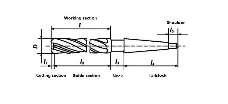
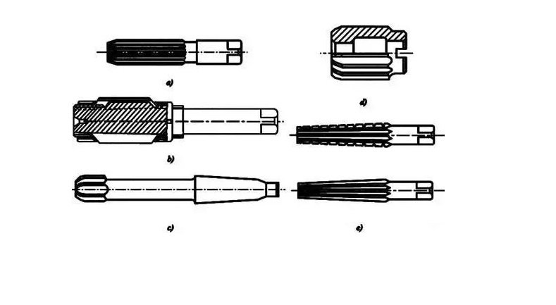
Reamers are generally divided into two types: hand reamers and machine reamers. The shank of a hand reamer is straight, and the working part is relatively long, providing good guidance. Hand reamers are further classified into solid type (Figure a) and adjustable outside diameter type (Figure b).
Machine reamers can be divided into shank types (Figure c: straight shank for diameters φ1–20mm, taper shank for diameters φ10–32mm) and shell types (Figure d). Reamers can machine not only round holes but also tapered holes using tapered reamers (Figure e).
Reaming Process and Its Applications
The allowance for reaming greatly affects the quality of the reamed hole. If the allowance is too large, the reamer experiences a heavy load, causing the cutting edges to dull quickly, making it difficult to obtain a smooth surface finish and maintain dimensional tolerance. If the allowance is too small, it cannot remove the tool marks left by the previous process, thus failing to improve the hole quality. Generally, rough reaming allowance is between 0.35 to 0.15 mm, while finish reaming allowance is between 0.15 to 0.05 mm.
To avoid the formation of a built-up edge, reaming is usually performed at relatively low cutting speeds (for high-speed steel reamers, machining steel and cast iron, cutting speed v < 8 m/min). The feed rate depends on the diameter of the hole being processed, the larger the hole diameter, the larger the feed rate. For high-speed steel reamers machining steel and cast iron, the feed is typically between 0.3 to 1 mm/rev.
During reaming, appropriate cutting fluid must be used for cooling, lubrication, and chip removal to prevent built-up edge formation and to clear chips in time. Compared to grinding and boring, reaming offers higher productivity and easier maintenance of hole accuracy. However, reaming cannot correct positional errors of the hole axis, so previous processes must ensure positional accuracy. Reaming is not suitable for stepped holes or blind holes.
The typical dimensional accuracy of reamed holes ranges from IT9 to IT7, and surface roughness Ra is generally between 3.2 to 0.8 μm. For medium-sized holes with relatively high precision requirements (such as IT7 accuracy holes), the drill–bore–ream process is a commonly used typical machining scheme in production.
Boring
Boring is a machining method that enlarges a pre-made hole using a cutting tool. Boring operations can be performed either on a boring machine or on a lathe.
Boring Methods
There are three different boring methods.
(1) The workpiece rotates while the cutting tool performs the feed motion.
The characteristics of this method are: after machining, the axis of the hole coincides with the rotation axis of the workpiece, the roundness of the hole mainly depends on the rotational accuracy of the machine spindle, the axial geometric error of the hole mainly depends on the positional accuracy of the tool feed direction relative to the rotation axis of the workpiece. This boring method is suitable for machining holes that require coaxiality with the external cylindrical surface.
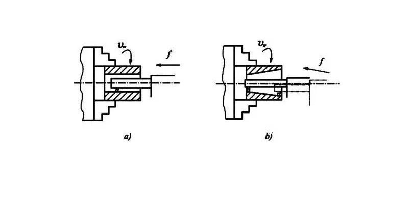
(2) Tool rotation, the workpiece for the feeding movement
The spindle of the boring machine drives the boring tool to rotate, and the table drives the workpiece to make a feeding movement.
(3) Tool rotation and feed movement
With this type of boring method, the length of the boring bar is changing, and the force deformation of the boring bar is also changing. The diameter of the hole near the spindle box is large, and the diameter of the hole away from the spindle box is small, forming a tapered hole. In addition, the boring bar extension length increases, the spindle, due to self-weight caused by the bending deformation, also increases, and the processed hole axis will produce the corresponding bending. This boring method is only suitable for processing shorter holes.
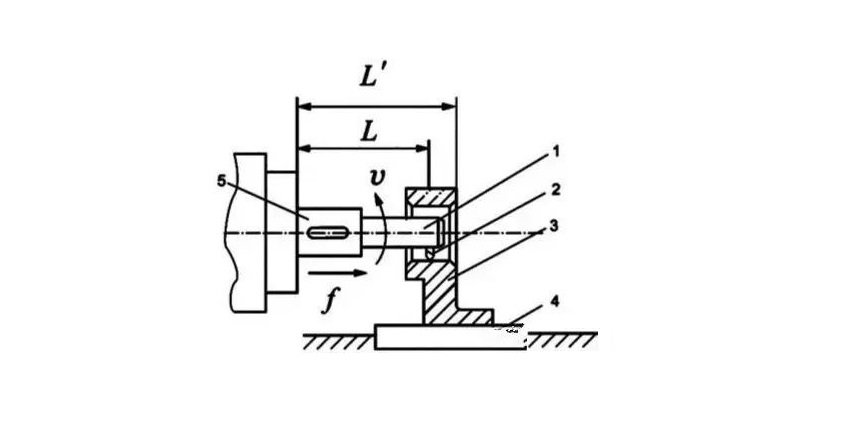
1-Boring bar 2-Boring tool 3-Workpiece 4-Table 5-Spindle
High Speed Fine Boring (Diamond Boring)
Compared with general boring, diamond boring is characterized by small back draft, small feed and high cutting speed, it can obtain high machining accuracy (IT7~IT6) and very smooth surface (Ra of 0.4 ~ 0.05μm). Diamond boring was initially processed with diamond boring tools, and now it is commonly processed with carbide, CBN and synthetic diamond tools. It is mainly used for machining non-ferrous metal workpieces, but can also be used for machining cast iron and steel parts.
Typical cutting parameters for diamond boring are:
- Backward depth of cut for rough boring: 0.2–0.6 mm.
- Final boring depth of cut: 0.1 mm.
- Feed rate: 0.01–0.14 mm/rev.
- Cutting speed for cast iron: 100–250 m/min.
- Cutting speed for steel: 150–300 m/min.
- Cutting speed for non-ferrous metals: 300–2000 m/min.
To ensure that diamond boring can achieve high machining accuracy and surface quality, the machine tool used (diamond boring machine) must possess high geometric accuracy and rigidity. The machine spindle bearings commonly use precision angular contact ball bearings or hydrostatic slide bearings, and high-speed rotating parts must be precisely balanced. In addition, the feed mechanism’s motion must be very smooth to ensure the worktable can perform stable, low-speed feed movement.
Diamond boring offers excellent machining quality and high production efficiency. It is widely used in mass production for the final machining of precision holes, such as engine cylinder bores, piston pin holes, and spindle holes in machine tool spindle boxes. However, it should be noted that when machining ferrous metal products with diamond boring, only carbide and CBN boring tools can be used. Diamond tools cannot be used because the carbon atoms in diamond have a strong affinity for iron-group elements, resulting in a short tool life.
Boring Tools
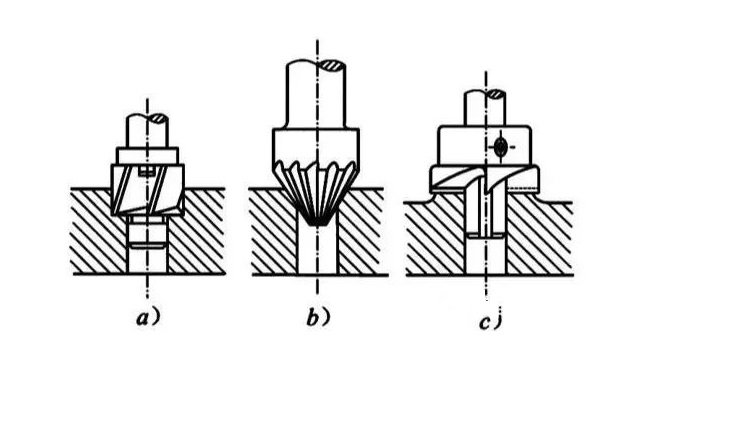
Boring tools can be divided into single-edged boring tools and double-edged boring tools. The single-edged boring tool (as shown in the figure) has a structure similar to a lathe tool and features only one main cutting edge. When boring with a single-edged boring tool, the hole size is controlled by the operator adjusting the position of the boring head.
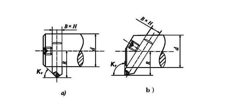
a)Single-edged boring tool for through holes
b)Single-edged boring tool for blind holes
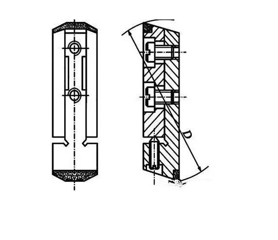
A double-edged boring tool has two symmetrical cutting edges, equivalent to two lathe tools symmetrically mounted and cutting simultaneously. The dimensional accuracy of the hole relies on the size of the boring tool itself. The floating boring tool shown in the figure is a type of double-edged boring tool. The boring inserts are mounted in the slots of the boring bar, and the opposing forces acting on the two cutting edges automatically balance their position. This can eliminate errors caused by tool mounting inaccuracies or boring bar runout. However, similar to reaming, it can only ensure dimensional accuracy and cannot correct positional errors of the hole axis before reaming.
Characteristics and Application Range of the Boring Process
Compared to the drill–bore–ream process, boring is not limited by the size of the cutting tool for hole diameter. Boring has strong error-correcting capability, it can correct the original hole axis deflection error through multiple passes, and can maintain high positional accuracy between the bored hole and the locating surface.
Compared to turning external cylindrical surfaces, due to the lower rigidity and greater deformation of the boring bar system, as well as poorer heat dissipation and chip removal conditions, thermal deformation of both the workpiece and tool is greater. Therefore, the machining quality and production efficiency of boring are not as high as those of external turning.
In summary, boring has a wide processing range and can machine holes of various sizes and accuracy grades. For holes and hole systems with large diameters and high requirements for dimensional and positional accuracy, boring is almost the only processing method. The machining accuracy of boring generally ranges from IT9 to IT7. Boring can be performed on boring machines, lathes, milling machines, and other machine tools, offering flexibility and mobility. It is widely used in production. In large-scale mass production, boring fixtures are often used to improve boring efficiency.
Honed Hole
Honing Principle and Honing Head
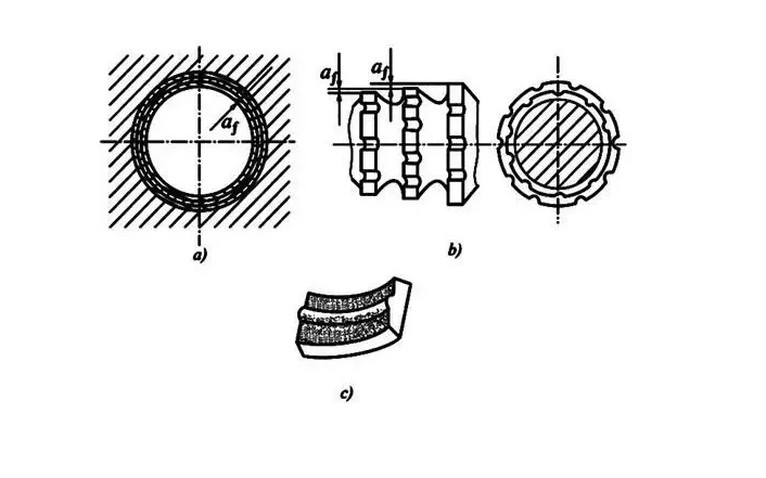
Honing is a finishing process that uses a honing head equipped with abrasive stones (grinding sticks) to smooth the surface of a hole. During honing, the workpiece is fixed in place while the honing head is driven by the machine spindle to rotate and perform a reciprocating linear motion. In the honing process, the abrasive stones apply a certain pressure to the workpiece surface, removing an extremely thin layer of material. The cutting path forms a crosshatched pattern.
To ensure that the abrasive particles’ motion paths do not repeat, the ratio between the honing head’s rotational speed (RPM) and the number of its reciprocating strokes per minute should be a pair of relatively prime numbers.
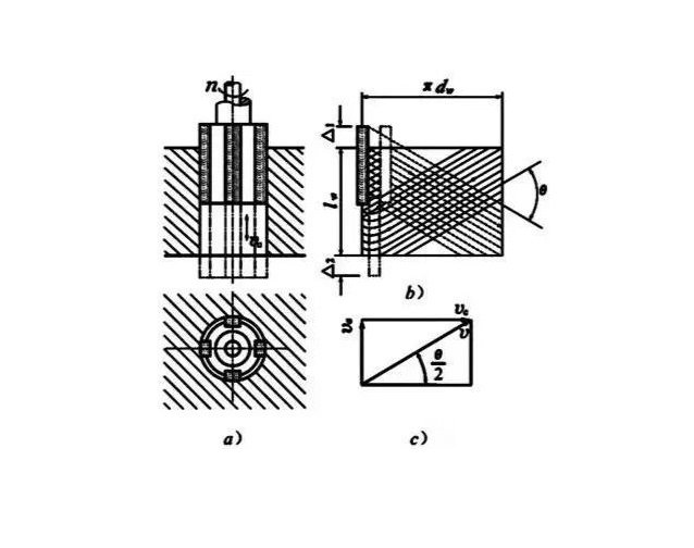
a) Forming motion b) Expansion of the grinding trajectory of the abrasive strip c) Synthetic velocity
The crossing angle of the honing trajectory is related to the reciprocating speed and the circumferential speed of the honing head. The size of this angle affects the machining quality and efficiency of honing. To facilitate the removal of fractured abrasive grains and chips, reduce cutting temperature, and improve machining quality, sufficient cutting fluid should be used during honing.
To ensure uniform machining of the entire hole wall, the stroke of the abrasive sticks should exceed the hole length at both ends by a certain over-travel amount. To guarantee uniform honing allowance and reduce the influence of spindle runout on machining accuracy, a floating connection is generally used between the honing head and the machine spindle. Manual, pneumatic, or hydraulic mechanisms can realize the radial expansion adjustment of the honing stones on the honing head.
Honing Process Characteristics and Application Range
1. Honing achieves high-dimensional and geometric accuracy, typically within IT7 to IT6 grades. The roundness and cylindricity errors of the hole can be controlled within 3 to 5 μm. However, honing does not improve the positional accuracy of the hole.
2. Honing produces excellent surface quality, with surface roughness Ra ranging from 0.2 to 0.025 μm. The depth of the surface metal’s damaged layer is minimal, about 2.5 to 25 μm.
3. Although the circumferential speed of the honing head is relatively low compared to grinding (vc = 16 to 60 m/min), the large contact area between the abrasive sticks and the workpiece combined with a relatively high reciprocating speed (va = 8 to 20 m/min) allows honing to maintain a high production rate.
Honing is widely used in mass production for the precision machining of engine cylinder bores and various hydraulic device holes. It can also machine deep holes with length-to-diameter ratios greater than 10. However, honing is not suitable for machining holes in ductile non-ferrous metal workpieces, nor for holes with keyways, splines, or similar features.
Broaching
Broaching and Broaches
Broaching is a high-productivity finishing method performed on a broaching machine using specially designed broaches. Broaching machines come in two types: horizontal broaching machines and vertical broaching machines, with horizontal broaching machines being the most common.
During broaching, the broach moves in a low-speed linear motion (the main cutting motion). The number of teeth engaged simultaneously on the broach is generally no less than three, otherwise, the broach’s operation is unstable and can easily cause circular ripples on the workpiece surface. To avoid excessive broaching force that may cause broach breakage, the number of teeth cutting simultaneously usually should not exceed 6 to 8.
There are three different broaching methods, described as follows:
1) Layered Broaching
This broaching method features the broach removing the machining allowance layer by layer sequentially. To facilitate chip breaking, the broach teeth are ground with staggered chip breakers. A broach designed according to the layered broaching method is called a conventional broach.
a) Broaching pattern b) Cutting part tooth shape c) Chips
2) Sectional Broaching
This broaching method features each layer of the machined surface being removed by a group of teeth with essentially the same size but staggered cutting edges (usually 2 to 3 teeth per group). Each tooth only removes a part of one layer of metal. Broaches designed according to the sectional broaching method are called circular pitch broaches.
3) Combined Broaching
This method combines the advantages of layered and sectional broaching. The rough cutting teeth adopt the sectional broaching method, while the finishing teeth use the layered broaching method. This design shortens the broach length and improves productivity while achieving better surface quality. Broaches designed according to the combined broaching method are called combined broaches.
Broaching Process Characteristics and Application Range
1) The broach is a multi-tooth tool that can sequentially complete roughing, finishing, and sizing in a single broaching stroke, resulting in high production efficiency.
2) The accuracy of broached holes mainly depends on the precision of the broach. Under normal conditions, broaching accuracy can reach IT9 to IT7, and surface roughness Ra can reach 6.3 to 1.6 μm.
3) During broaching, the workpiece is positioned by the hole being machined itself (the leading part of the broach acts as the locating element). Broaching cannot easily guarantee the positional accuracy between the hole and other surfaces. For rotational parts requiring coaxiality between internal and external cylindrical surfaces, broaching is usually performed first, and then the other surfaces are machined using the hole as the datum.
4) Broaches can machine not only round holes but also formed holes and spline holes.
5) Broaches are fixed-dimension tools with complex shapes and high costs, making them unsuitable for machining large holes.
Broaching is commonly used in mass production for through holes with diameters of φ10–80 mm and hole depths not exceeding 5 times the diameter, mostly in small to medium-sized parts.
Summary
Drilling Characteristics: Poor tool rigidity, difficult chip evacuation, and heat dissipation.
Boring Characteristics:
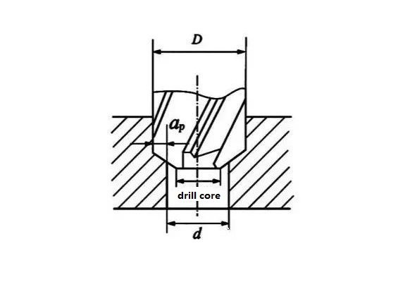
① Cutting edge does not need to extend from the outer diameter to the center, avoiding influence from the cross-cutting edge.
② Small depth of cut (ap), narrow cutting width, easy chip removal, chip flutes can be made smaller and shallower, increasing tool rigidity.
③ High productivity, good guidance, and stable cutting.
④ Higher machining quality than drilling.
Reaming Characteristics: Good tool rigidity and guidance, small reaming allowance, low cutting force and speed (vc), less cutting heat, reducing workpiece heating and deformation, suitable for finishing.
Additionally, drilling, boring, and reaming can only guarantee the accuracy of the hole itself, but not the positional accuracy between holes. At this time, fixtures or boring fixtures can be used to ensure positional accuracy.
YPMFG Machining
YP-MFG is a leading manufacturer specializing in high-precision metal parts and CNC machining services. You Design It, We’ll Make It.