Forging has a long history, which has been perpetuated by handmade workshop production. It was probably at the beginning of the 20th century. It is only gradually that mechanical industrialization of production in the railroad, military industry, shipbuilding and other industries. The main symbol of this transformation was the use of machines with powerful forging capabilities.
Table of Contents
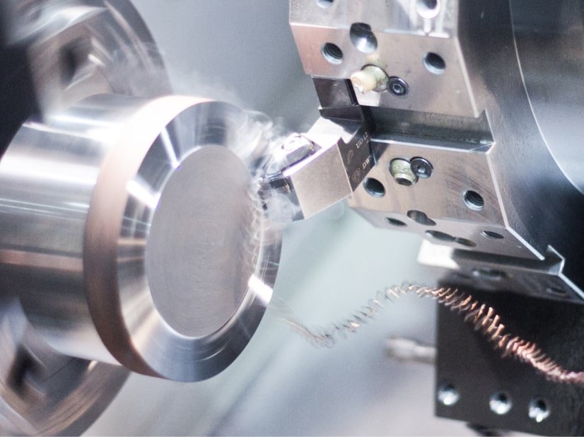
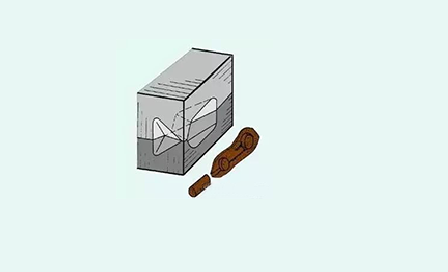
In the process of automobile manufacturing, the processing method of forging is widely used. With the progress of science and technology, the requirements for workpiece precision continue to improve, with high efficiency, low cost, low energy consumption, high quality and other advantages of precision forging technology being more and more widely used. According to the different deformation temperatures during the plastic forming of metals, precision cold forging can be divided into cold forging, temperature forming, sub-hot forging, hot precision forging, etc. The automobile parts produced include: automobile clutch engagement ring, automobile transmission input shaft parts, bearing rings, automobile constant velocity universal joint slip sleeve series products, automobile differential gears, automobile front axle and so on.

I. Definition and Classification of Forging
1. The definition of forging
Forging is a uses forging machinery to exert pressure on the metal billet, so that it produces plastic deformation to obtain certain mechanical properties, a certain shape and size of the forging processing method. Forging (forging and stamping) is one of the two major components.
Through forging, the metal in the smelting process is produced in a cast state with loose and other defects, optimizing the microstructure of the organization, and at the same time, due to the preservation of the complete metal flow, the mechanical properties of forgings are generally better than the same material castings. Related machinery in the high load, severe working conditions of important parts, in addition to the shape of the simpler available rolled plates, profiles or welded parts, more forgings.
2. The classification of forging
According to the different production tools, they can be divided into free forging technology, modular forging, mill ring and special forging.
Free forging: refers to the use of simple general-purpose tools, or in the forging equipment on and off the anvil, iron directly between the billet to apply external forces, so that the billet deformation and obtain the required geometry and internal quality of the forging processing methods.
Die forging: refers to the metal billet being placed in a certain shape of the forging die chamber pressure deforms the billet and obtains forgings. Die forging can be divided into hot forging, warm forging and cold forging. Warm forging and cold forging are the future development direction of die forging, and also represent the level of forging technology.
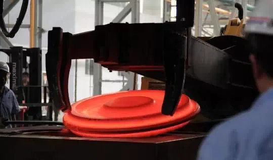
Ring milling: refers to the production of ring-shaped parts of different diameters by a special equipment ring milling machine, also used for the production of automobile wheels, train wheels and other wheel-shaped parts.
Special forging: including roll forging, wedge cross rolling, radial forging, liquid die forging, and other forging methods, these methods are more suitable for the production of certain special shape parts. For example, roll forging can be used as an effective pre-forming process, significantly reducing the subsequent molding pressure, wedge rolling can produce steel balls, drive shafts and other parts, radial forging can produce large gun barrels, step shafts and other forgings.
According to the forging temperature, the forging technology can be divided into hot forging, warm forging and cold forging.
The beginning of recrystallization temperature of steel is about 727 ℃, but 800 ℃ is commonly used as a dividing line, higher than 800 ℃ is hot forging, between 300 and 800 ℃ is called warm forging or semi-hot forging. Forging at room temperature is called cold forging. Used in most industries, forging is hot forging, warm forging and cold forging is mainly used in automobiles, general machinery and other parts of the forging. Warm forging and cold forging can be effective in saving material.
According to the movement of the forging die, forging can be divided into pendulum rolling, pendulum rotary forging, roll forging, wedge rolling, rolling ring, inclined rolling and so on.
3. Forging materials
Forging material is mainly a variety of components of carbon steel and alloy steel, followed by aluminum, magnesium, copper, titanium and other alloys, iron-based high-temperature alloys, nickel-based high-temperature alloys, cobalt-based high-temperature alloys of deformation alloys are also used in the forging or rolling way to complete the alloy, but these alloys because of the plasticity of its relatively narrow area, so the forging will be more difficult to forge the different materials, heating temperature, the opening temperature of the forging temperature and end of the forging temperature have strict requirements.
The original state of the material is bar, ingot, metal powder and liquid metal. The ratio of the cross-sectional area of the metal before deformation to the cross-sectional area after deformation is called the forging ratio.
Correct choice of forging ratio, reasonable heating temperature and holding time, reasonable beginning and final forging temperature, reasonable amount of deformation and deformation speed to improve product quality and reduce costs have a great relationship.
Ⅱ. Commonly Used Forging Methods and Advantages and Disadvantages
1. Free Forging
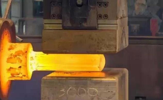
Free forging refers to the use of simple general-purpose tools, or the forging equipment on and off the anvil iron, directly between the billet to apply external forces, so that the billet is deformed and obtains the desired geometric shape and internal quality of the forging processing methods. The free forging method of production of forgings is called free forging.
Free forging is based on the production of a small batch of forgings, the use of forging equipment such as forging hammers, hydraulic presses and other forging equipment in the billet molding process, to obtain qualified forgings. The basic processes of free forging include upsetting, elongation, punching, cutting, bending, twisting, misalignment and forging. Free forging adopts the hot forging method.
Free Forging Process
It includes basic process, auxiliary process and finishing process.
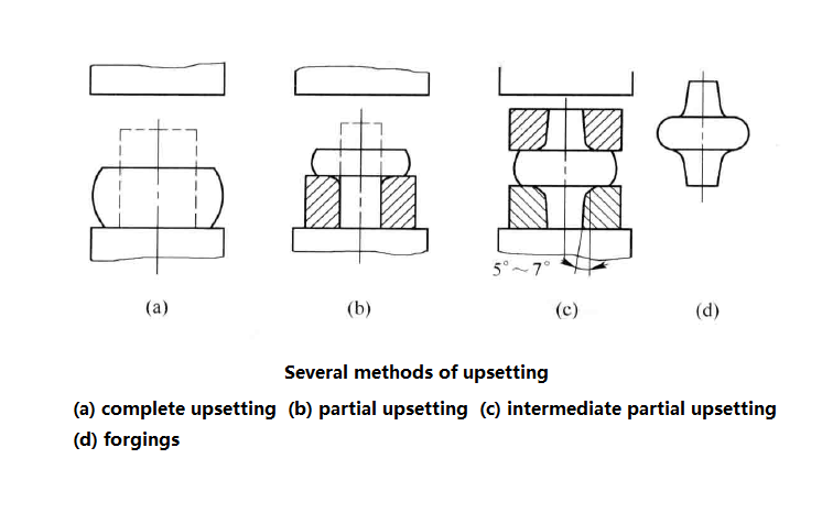
The basic processes of free forging: upsetting, elongation, punching, bending, cutting, twisting, misalignment and forging, etc., while the most commonly used in actual production are upsetting, elongation, punching and these three processes.
Auxiliary process: Pre-deformation process, such as pressing jaws, pressing ingot edges, cutting shoulders and so on.
Finishing process: the process of reducing surface defects of forgings, such as removing surface unevenness and shaping forgings.
| No. | Operation Name | Definition | Operating Rules | Applications |
| Upsetting | (1) Full Upsetting (2) Local Upsetting (3) Upsetting with End Taper (4) Flattening Upset | (1) A forging process where the billet height decreases and cross-section increases. (2) Local upsetting refers to deforming only part of the billet. | (1) The height-to-diameter ratio (h₀/d₀) should be ≤ 2.5 to avoid buckling. (2) Heating must be uniform for even deformation. (3) The upsetting surface must be perpendicular to the billet axis. | (1) Used for parts with low height and large cross-section, such as gears, discs, impellers. (2) Pre-process before punching. (3) To increase the forging ratio for subsequent elongation. |
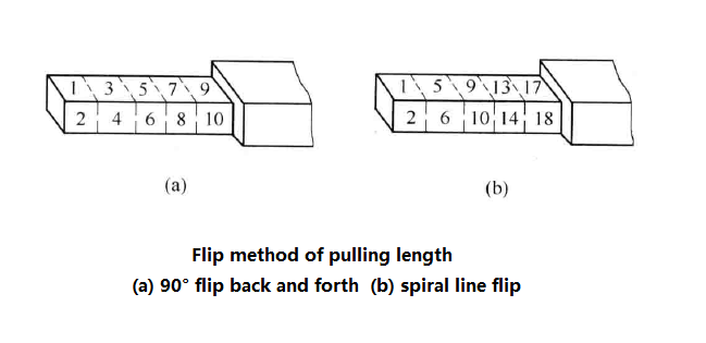
| Drawing Out | (1) Drawing Out (2) Mandrel Drawing Out (3) Mandrel Hole Expanding | (1) Reduces billet cross-section and increases its length. (2) For hollow billets, reduces wall thickness and outer diameter while increasing length using a mandrel. (3) Expands both inner and outer diameters using a mandrel instead of a bottom anvil. | (1) Contact length I < a₀, the smaller, the higher the efficiency (I = 0.4–0.8b). (2) Width-to-height ratio (a/h) ≤ 2.5 to prevent billet flipping. (3) Rotate the billet continuously during drawing out. (4) For mandrel hole expanding, d ≥ 0.35L, mandrel must be smooth. | (1) Used for long, slender parts like shafts, tie rods, crankshafts. (2) For hollow parts such as gun barrels, turbine shafts, rings, and sleeves. |
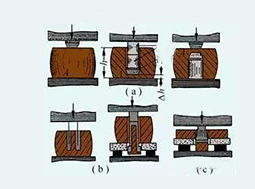
| Punching | (1) Solid Punch Piercing (2) Hollow Punch Piercing (3) Plate Piercing | Piercing through or partially into a billet to create holes. | (1) Piercing surface must be flattened. (2) Piercing depth △h = 15–20% of billet height, for large holes, △h ≥ 100–160mm. (3) For holes < 450mm, use a solid punch. (4) Avoid piercing for holes < 25mm. | (1) Used to make hollow components like gear blanks, rings, sleeves. (2) For large high-precision forgings (e.g., turbine shafts), hollow punching is preferred. |
Advantages:
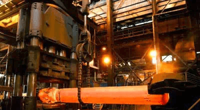
The forging is flexible and can produce small parts of less than 100kg as well as heavy parts as large as 300t or more.
The tools used are simple and universal.
Forging forming is to make the billet subregional gradual deformation, therefore, forging the same forgings requires forging equipment tonnage than the model forging is much smaller.
Low precision requirements for equipment.
Short production cycle.
Disadvantages and limitations:
Production efficiency is much lower than model forging.
Simple shape, low dimensional accuracy and rough surface of forgings, high labor intensity of workers, and also a high technical level are required.
It is not easy to realize the mechanization and automation.
2. Die forging
Die forging refers to the use of die forging equipment in a special die forging blank forming process, and obtaining forgings through forging methods. This method of production of forgings accurate size, processing allowance is small, the structure is also more complex high productivity.
Classified according to the different equipment used: hammer die forging, crank press die forging, flat forging machine die forging and friction press die forging.
The most commonly used equipment for die forging on the hammer is a steam-air die forging hammer, an anvil seat hammer and a high-speed hammer.
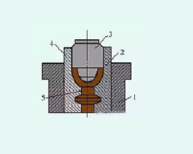
Forging die mold:
According to its different functions can be divided into two categories of die forging and billet making die chamber.
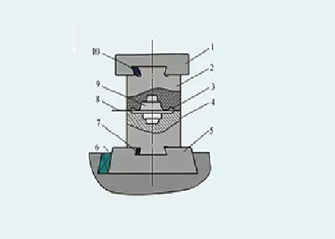
(1-Hammer head 2-Upper die 3-Flying edge groove 4-Lower die 5-Die pads 6, 7, 10-Fastening sprags 8-Split die face 9 -die chamber)
1) Die forging chamber
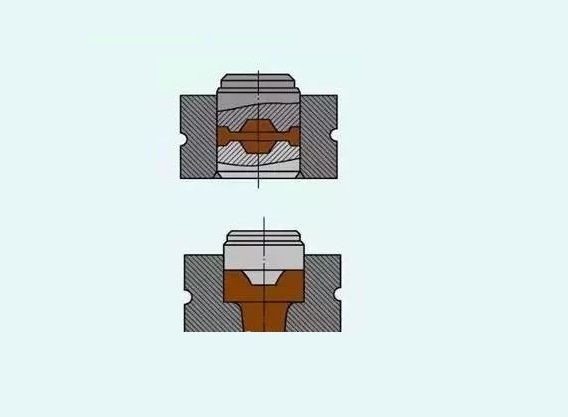
(1) Pre-forging die chamber:
The role of the pre-forging die chamber is to deform the blank to close to the shape and size of the forgings, so that in the final forging, the metal can easy to fill the die chamber and get the size of the forgings required. For the simple shape of the forgings, or batch size is not set up pre-forging die chamber. Pre-forging die chamber round angle and slope than the final forging die chamber is much larger, and there is no fretting groove.
(2) Final forging die chamber:
The role of the final forging die chamber is to make the final deformation of the blank to the required shape and size of the forging, therefore, its shape should be the same as the shape of the forging, but because of the forging cooled to contraction, so the size of the final forging die chamber should be enlarged than the size of the forging a contraction. The shrinkage of steel forgings is taken as 1.5%. In addition, along the die chamber around the fringe groove, to increase the resistance of the metal from the die chamber, prompting the metal to fill the die chamber, while accommodating the excess metal.
2) Billet die chamber
For the complex shape of the forging, in order to ensure that the blank shape is basically in line with the shape of the forging, so that the metal can be reasonably distributed and well filled with the die chamber, it is necessary to make blanks in advance in the blanking die chamber.
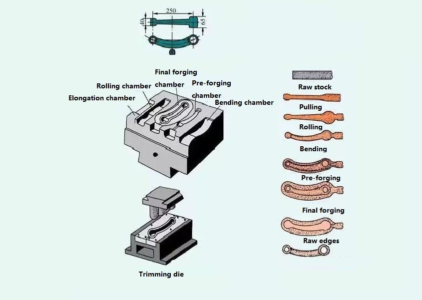
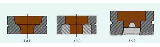
(1) Elongated die chamber:
It is used to reduce the cross-sectional area of a part of the blank in order to increase the length of that part. There are two types of elongation chambers: open type and closed type.
(2) Rolling die chamber:
It is used to reduce the cross-sectional area of one part of the blank in order to increase the cross-sectional area of another part so that the metal is distributed according to the shape of the forging. The rolling die chamber is divided into two types: open and closed.
(3) Bending chamber:
For bent rod type die forgings, a bending chamber is required to bend the blank.
4) Cutting off the mold chamber:
It is in the corner of the upper mold and the lower mold to form a pair of knife mouths, used to cut off the metal.
Pros:
Higher productivity. When die forging, the deformation of the metal is carried out in the die chamber so that it can obtain the required shape faster.
Can forge complex shapes of forgings, and can make the metal flow distribution more reasonable, improving the service life of parts.
The size of the die forging parts is more accurate, the surface quality is better, and the machining allowance is smaller.
Save metal materials, reduce cutting and processing workload.
Under the condition of sufficient batch, it can reduce the cost of parts.
Cons and limitations:
The weight of die forging parts is limited by the capacity of general die forging equipment, mostly below 70 kg.
The manufacturing cycle of forging dies is long and costly.
The investment cost of die forging equipment is larger than that of free forging.
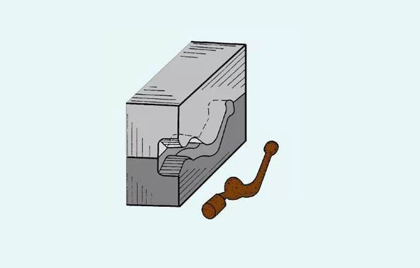
3. Roll forging
Roll forging refers to a pair of rotating fan-shaped molds to produce plastic deformation of the billet, so as to obtain the required forgings or forging billet forging process.
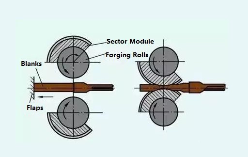
The principle of roll forging deformation is shown above. Roll forging deformation is a complex three-dimensional deformation. Most of the deformed material flows along the length direction so that the length of the billet increases, and a small part of the material flows laterally so that the width of the billet increases. The root cross-sectional area of the billet is decreasing during the roll forging process. Roll forging is suitable for shaft parts elongation, slab rolling and distribution of material along the length and other deformation processes.
Roll forging can be used in the production of connecting rods, twist drill bits, wrenches, nails, hoes, picks and turbine blades. Roll forging process utilizes the rolling forming principle to deform the blank gradually.
Compared with ordinary die forging, roll forging has a simpler equipment structure, smooth production, vibration and noise, easy to realize automation, and high production efficiency.
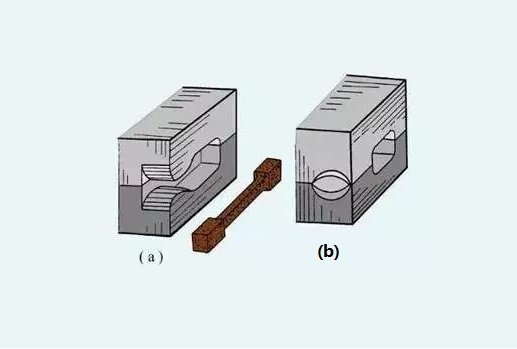
4. Tire die forging
Tire die forging is the use of free forging method of making blanks, and then in the final shape of the tire mold in a forging method, is between free forging and die forging between a forging method. In the die forging equipment is less, and most of the free forging hammers for small and medium-sized enterprises are commonly used.
Tire mold forging uses a lot of types of molds, commonly used in the production of: type fall, buckle mold, set of molds, cushion mold, mold, etc.
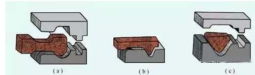
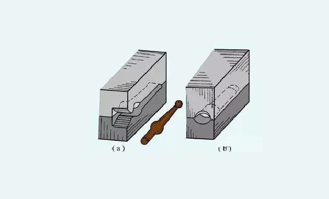
Closed cylinder mold is mostly used for the forging of rotary forgings. Such as gears with two end surfaces with tabs, etc., and sometimes also used for non-rotary forgings. Closed cylinder die forging is not flying edge forging.
For the complex shape of the tire die forgings, it is necessary to add two half-molds in the cylinder die (i.e., increase the die surface), made of a combination of the cylinder die, blanks in the two half-mold mold chambers, formin
(c) Cylinder Die with Spacer
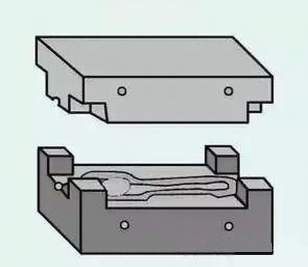
The combined film usually consists of two parts: the upper and lower molds. In order to make the upper and lower molds coincide and not make the forgings produce misalignment, guide pillar and guide pin positioning are used. Combined mold is used to produce complex shapes of non-rotary forgings, such as connecting rods, fork forgings and so on.
Tire die forging has the following advantages compared with free forging:
As the blank in the die chamber is formed, the forging size is more accurate, the surface is more polished, the distribution of streamline organization is more reasonable, so the quality is higher.
Tire die forging can forge a more complex shape of the forgings, because the die chamber controls the shape of the forgings, so the billet forming faster, with higher productivity than free forging 1 to 5 times.
Fewer remaining pieces, and thus less machining allowance, which can save metal materials and reduce machining hours.
Disadvantages and limitations:
Need a larger tonnage of forging hammer.
Can only produce small forgings.
The service life of the tire mold is low.
Work generally relies on manpower to move the mold, and therefore is more labor-intensive.
Tire die forging for the production of medium and small batch forgings.
Ⅲ. Forging Defects and Analysis
Forging raw materials for ingots, rolling material, extrusion material and forging billet. The rolling material, extrusion material and forging billet are ingots processed by rolling, extrusion and forging, processed into semi-finished products. In general, the appearance of internal defects or surface defects of ingots is sometimes unavoidable. Coupled with the improper forging process in forging process, ultimately resulting in forgings containing defects. The following briefly introduces some common defects in forgings.
1. Defects in forgings caused by defects in the raw material are usually
Surface cracks
Surface cracks occur mostly in rolled bars and forged bars, generally in a straight line shape, and rolling or forging of the main deformation direction. Caused by many reasons for this defect, for example, the ingot of subcutaneous bubbles in the rolling side of the deformation along the direction of the elongation of one side, the other side of the exposure to the surface and the internal depth of the development. Another example is in rolling, the surface of the billet, such as scratched, cooling will cause stress concentration, which may crack along the scratches and so on. This kind of crack, if not removed before forging, may be extended to cause forging cracks.
Folding
The reason for the formation of folding is when the metal billet in the rolling process, due to the rolls on the groove sizing is not correct, or due to groove wear surface burrs produced in the rolling was involved in the formation and the surface of the material into a certain angle of folding seam. For steel, there are iron oxide inclusions within the folding seam and decarburization around it. Folding may cause folding or cracking of the forging if not removed before forging.
Scarring
Scarring is a peelable film in a localized area on the surface of the rolled material.
The formation of scarring is due to the casting of liquid steel splash and condensation on the surface of the ingot, rolling is pressed into a thin film, adhering to the surface of the rolled material, that is, scarring. After forging forgings by pickling cleaning, the film will be peeled off and leaving the surface defects of forgings.
Layer fracture
Laminar fracture is characterized by its fracture or section with the broken slate, bark is very similar.
Laminar fracture occurs in alloy steel (chrome-nickel steel, chrome-nickel tungsten steel, etc.), and carbon steel is also found. This defect is due to the presence of non-metallic inclusions in the steel, dendritic crystal segregation, as well as porosity and other defects in the forging and rolling process, along the direction of rolling is elongated occurs, so that the steel is lamellar. If there are too many impurities, forging there is a risk of laminar fracture. The more serious the laminated fracture, the worse the plasticity and toughness of the steel, especially the transverse mechanical properties, are very low, so the steel is unqualified if it has obvious laminar defects.
Bright line (bright area)
A bright line is presented in the longitudinal fracture of the crystalline shiny reflective ability of the thin line, most prominent through the entire fracture, most produced in the axial part.
Bright lines are mainly due to alloy segregation. Slightly bright lines have little effect on mechanical properties, but serious bright lines will significantly reduce the plasticity and toughness of the material.
Non-metallic inclusions
Non-metallic inclusions are mainly formed during the cooling process of the molten or cast steel water due to chemical reactions between the components or between the metal and the furnace gas or container. In addition, in the metal melting and casting, due to refractory materials that fall into the liquid steel can also form inclusions, which inclusions collectively referred to as slag. In the cross-section of the forging, non-metallic inclusions can be point, sheet, chain or mass distribution. Serious inclusions can easily cause cracking of the forging or reduce the performance of the material.
Carbide segregation
Carbide segregation is often found in alloy steels with high carbon content. It is characterized by more carbide aggregates in the local area. It is mainly in the steel of the eutectic carbides and secondary mesh carbides in the steel, in the open billet and rolling is not broken and uniform distribution caused by. Carbide segregation will reduce the steel forging deformation performance, easy cause forgings to crack. Forging heat treatment quenching is prone to localized overheating, overcooking and quenching cracking.
Aluminum alloy oxide film
Aluminum alloy oxide film is generally located in the die forging parts on the web and near the die surface. In the low times the organization is a micro-fracture, in the high times the organization is a vortex-like, in the fracture characteristics can be divided into two categories: one, is a flat sheet, the color from silver gray, light yellow until brown, dark brown. Second, is a small dense and with the glitter of the dots.
Aluminum alloy oxide film is open in the casting process of the melt liquid surface, and atmospheric water vapor or other metal oxides formed during the interaction of the oxide film in the transcasting process are rolled people inside the liquid metal formed.
Forging and die forging parts in the oxide film on the longitudinal mechanical properties do not have a significant impact, but in the height direction, mechanical properties have a greater impact, which reduces the height direction strength properties, especially the height direction of the elongation, impact toughness and height direction corrosion resistance properties.
White spots
Round or oval silvery-white spots on the longitudinal fracture of the billet and small cracks on the transverse fracture mainly characterize white spots. The size of the white spots varies in length from 1 to 20 mm or longer. White spots are common in alloy steels such as nickel-chromium and nickel-chromium-molybdenum steels, and are also found in ordinary carbon steels, where they are hidden internal defects. White point is produced under the combined effect of hydrogen and phase transformation when the organizational stresses and thermal stresses, when the steel contains more hydrogen and hot pressure processing after cooling (or forging after heat treatment) is too fast easier to produce.
With the white point of steel forging out of the forging, in the heat treatment (quenching) prone to cracking, and sometimes even fall into pieces. White point reduces the plasticity of steel and the strength of the parts, which is a stress concentration point, it is like a sharp cutter. Under the action of alternating loads, it is easy to form fatigue cracks and lead to fatigue damage. So, white point is absolutely not allowed in forging raw material.
Coarse crystal ring
A coarse crystal ring is often a defect that exists on aluminum alloy or magnesium alloy extruded bars.
After heat treatment supply of aluminum, magnesium alloy extrusion bar, in its round section of the outer layer often has a coarse crystal ring. The thickness of the coarse crystal ring is gradually increasing from the beginning to the end of the extrusion. If the lubrication conditions during extrusion are good, the coarse crystal ring can be reduced or avoided after heat treatment. On the contrary, the thickness of the ring will increase.
The cause of rough crystal rings is related to many factors. However, the main factor is due to the friction between the metal and the extrusion barrel during the extrusion process. This friction results in the extruded bar having a cross-section where the outer layer of grains is much more broken than the grains in the center of the bar. However, due to the influence of the cylinder wall, this area of low temperature, extrusion failed to recrystallize fully, quenching and heating, grain recrystallization and growth have been recrystallized grains and swallowed, so in the surface layer of the formation of a coarse crystal ring is formed.
Coarse crystal ring billet forging is easy to crack, as coarse crystals are environmentally friendly to stay in the forging surface layer, which will reduce the performance of the parts.
Shrinkage residue
Shrinkage residue is generally due to the ingot riser part of the centralized shrinkage holes produced by the failure to remove clean, open billet and rolling residual inside the steel and produce.
Dense inclusions, loosening or segregation generally characterize the area around the shrinkage residue. Gaps that appear as irregular wrinkles in the transverse low times. Susceptible to cracking of forgings during forging or heat treatment.
2. Defects arising from improper material preparation and their effect on forgings
There are several kinds of defects produced by improper material preparation.
Skewing
Skewing is in the sawing machine or punching machine when the material, due to the bar, is not pressed, resulting in the billet end face relative to the longitudinal axis of the inclination of the amount of more than the specified permissible value. In severe cases, folding may occur during the forging process.
Bent billet ends with burrs
In the shearing machine or punching machine under the material, due to scissor blade or cut off the gap between the edge of the mold is too large or due to the edge of the edge is not sharp, so that the blank in the cut off before there has been bending, as a result, part of the metal is squeezed into the gap between the blade or mold, the formation of end sag burrs.
Burr of the blank, heating is easy to cause local overheating, overcooking, forging is easy to produce folding and cracking.
Blank end face depression
In the shear bed loading and unloading, due to the gap between the scissor blade is too small, the metal section of the upper and lower cracks do not overlap, resulting in a secondary shear, the result is that part of the end of the metal is pulled off, the end face into a concave shape. Such a billet is prone to folding and cracking when forging.
End cracks
In the cold shear large large-section alloy steel and high-carbon steel bars, often in the shear after 3 ~ 4h found end cracks are found, mainly due to the unit pressure of the blade being too large, so that the round section of the billet flattened into an oval, when the material produced a large internal stress. And the flattened end seeks to restore the original shape, under the action of internal stress is often in the cut material within a few hours after the crack. Material hardness is too high, uneven hardness and material segregation are more serious, when also easy to produce shear cracks.
Blanks with end cracks will further expand when forged.
Gas cutting cracks
Gas cutting cracks are generally located at the end of the billet is due to gas cutting occurs before the raw material is preheated, which causes tissue stress and thermal stress caused by.
Billets with gas-cut cracks will be further extended when forging. Therefore, it should be removed before forging.
Convex core cracking
When the lathe is discharged, there is often a convex core in the center of the end face of the bar. Forging process, due to the convex core of the section, is very small, the cooling is very fast, and thus its plasticity is low, but the billet matrix part of the section is large, the cooling is slow, high plasticity. Therefore, in the section of the sudden change in the junction of the stress concentration of the parts, coupled with the two parts of the plasticity, the difference is large, so under the action of the hammering force, the convex core of the surrounding easy to crack.
3. Defects often produced by the improper heating process
Defects arising from improper heating can be divided into:
(1) The medium affects the outer layer of the billet organization and chemical state changes caused by defects, such as oxidation, decarburization, carbonization and sulfurization, copper infiltration, etc..
(2) Defects caused by abnormal changes in the internal organization and structure, such as overheating, overcooking and failure to heat through.
(3) Due to uneven distribution of temperature within the billet, causing internal stress (such as temperature stress, tissue stress) that is too large and billet cracking.
The following describes several of the common defects.
Decarburization
Decarburization refers to the metal at high temperatures in the surface layer of carbon is oxidized, so that the carbon content of the surface layer than the internal phenomenon of a significant decrease.
The depth of the decarburization layer with the composition of steel, furnace gas composition, temperature and holding time at this temperature. The use of oxidizing atmosphere heating is prone to decarburization. High carbon steel is also prone to decarburization, the steel containing more silicon is also prone to decarburization.
Decarburization reduces the strength and fatigue properties of the part, and wear resistance is weakened.
Carbonization
The forging heated by the oil furnace often in a surface or part of the surface carbonization phenomenon. Sometimes the thickness of the carbon layer of 1.5 ~ 1.6mm, the carbon content of the carbon layer of 1% (mass fraction) or so, the local point of the carbon content or even more than 2% (mass fraction), the appearance of Leistungenstein organization.
This is mainly in the case of oil furnace heating, when the position of the billet near the nozzle of the furnace or in the two nozzles cross spray fuel oil in the region, due to the oil and air mixing is not very good, and thus the combustion is incomplete, the result in the billet surface formation of reducing carburizing atmosphere, resulting in the effect of the surface of the carburization.
Carbonization makes the machinability of the forging worse, and it is easy to hit the knife when cutting.
Overheating
Overheating refers to the metal billet heating temperature being too high, or in the specified forging and heat treatment temperature range staying too long, or due to the thermal effect of the temperature rise being too high and causing the phenomenon of grain coarsening.
Carbon steel (sub-eutectic or over-eutectic steel) tends to appear after overheating, Wei’s organization. Martensitic steel, after overheating, often exhibits an intragranular structure, and die steel often to carbide angularization as a characteristic of overheating organization. Titanium alloy after overheating, there are obvious β-phase grain boundaries and flat, straight, elongated Wei’s organization. Alloy steel fractures after overheating will appear as stone fractures or strip fractures. Superheated organization, due to coarse grain size, will cause a reduction in mechanical properties, especially impact toughness.
General overheating of structural steel after normal heat treatment (normalizing, quenching), the organization can be improved, and the properties are restored, this overheating is often referred to as unstable overheating and the serious overheating of alloy structural steel by the general normalizing (including high temperature normalizing), annealing or quenching treatment, the overheating organization can not be eliminated, this overheating is often referred to as stable overheating.
Overcooking
Overcooking refers to the metal billet heating temperature is too high or in the high-temperature heating zone stays too long, the furnace oxygen and other oxidizing gases penetrate the metal grain gap, and oxidation of iron, sulfur, carbon, etc., the formation of fusible oxides co-crystalline, destroying the connection between the grains, so that the plasticity of the material is reduced sharply. Overcooking serious metal, withdraw coarse when gently hit on the crack, draw long, will appear in the overcooking transverse cracks.
There is no strict temperature boundary between overcooking and overheating. Generally characterized by oxidation and melting of the grain to determine overheating. For carbon steel, overcooking when the grain boundary melts, severe oxygen chemical mold steel (high-speed steel, Cr12 steel, etc.), overcooking, the grain boundary due to melting and appears fishbone-like lei’s body. Aluminum alloy overcooking appears grain boundary melting triangle and a re-melting ball. Forgings overcooked, often can not be saved, have to be scrapped.
Heating cracks
In the heating of large cross-section size of large ingots and poor thermal conductivity of high-alloy steel and high-temperature alloy billets, if the low-temperature stage of the heating rate is too fast, the billet due to the temperature difference between the inside and outside the temperature is large and produces a lot of thermal stress. Coupled with the billet at this time due to the low temperature and poor plasticity, if the value of thermal stress exceeds the strength limit of the billet, it will produce radial heating cracks from the center to the surrounding, so that the entire section is cracked.
Copper brittle
Copper embrittlement is cracked on the surface of the forging. When observed at high magnification, there is a yellowish copper (or copper solid solution) distributed along the grain boundaries.
Billet heating, such as the furnace residual copper oxide chips, oxidized steel at high temperatures, reduced to free copper, molten steel atoms along the austenite grain boundaries, expansion, weakening the connection between the grains. In addition, the steel contains a higher amount of copper [> 2% (mass fraction)], such as heating in an oxidizing atmosphere, the formation of a copper-rich layer under the iron oxide skin, also caused by steel brittleness.
4. Defects often produced by the improper forging process
Improper forging process usually produces the following defects.
Large grain
Large grain is usually due to the beginning of the forging temperature being too high, and the degree of deformation is not enough, or the final forging temperature is too high, or the degree of deformation falls into the critical deformation zone caused by. The aluminum alloy deformation degree is too large, resulting in weaving, the high-temperature alloy deformation temperature is too low, and the formation of mixed deformation of the organization may also cause coarse grains.
Coarse grain will reduce the plasticity and toughness of forgings and fatigue performance.
Uneven grain
Uneven grain refers to some parts of the forging grain is particularly coarse, while some parts are smaller. Uneven grain is the main reason for the billet deformation is not uniform in all places so that the degree of grain fragmentation is not the same, or the degree of deformation of local areas fall into the critical deformation zone, or high-temperature alloys local work hardening, or quenching and heating of the local grain coarseness. Heat-resistant steel and high-temperature alloys are particularly sensitive to grain inhomogeneity. Grain inhomogeneity will make the durability of the forging, fatigue performance decrease significantly.
Cold hardening phenomenon
Forging deformation due to low temperature or deformation speed is too fast, as well as forging cooling too fast, may make the recrystallization caused by softening can not keep up with the deformation caused by the strengthening (hardening), so that after hot forging forgings are still partially retained within the cold deformation of the organization. The existence of this organization improves the strength and hardness of the forging, but reduces the plasticity and toughness. Severe cold hardening phenomenon may cause forging cracks.
Crack
Forging cracks are usually caused by the presence of large tensile, shear or additional tensile stresses during forging. Cracks usually occur in the billet where the stress is greatest and the thickness is thinnest. If the billet surface and internal micro-cracks, or billet within the existence of organizational defects, or improper thermal processing temperature so that the plasticity of the material to reduce, or the deformation rate is too fast, the degree of deformation is too large, more than the material allows the plasticity of the pointer, etc., then in the withdrawal of coarse, drawing long, punching, reaming, bending and extrusion processes may produce cracks.
Cracking
Forging cracks are shallow, turtle-like cracks on the surface of the forging. Surfaces subjected to tensile stresses in the forming of forgings (e.g., unfilled projections or parts subjected to bending) are most susceptible to this defect.
The internal causes of tortoise cracking may be multifaceted:
(1) The material combines too much Cu, Sn and other fusible elements.
(2) high temperature heating for a long time, copper precipitation on the surface of the steel material, surface grain coarseness, decarburization, or the surface after multiple heating.
(3) Fuel sulfur content is too high, and there is sulfur penetration into the steel surface.
Fly edge cracks
Forging fissure is die forging and cutting-edge cracks produced in the parting surface of the mold. Flying edge cracks may be due to: ① in the die forging operation, due to heavy impact on the metal strong flow through the phenomenon. ② The magnesium alloy die forging cutting edge temperature is too low, the copper alloy die forging cutting edge temperature is too high.
Cracks on the die face
Forging split die surface crack refers to the crack along the forging split die surface. Raw material non-metallic inclusions, die forging to the die surface flow and concentration or shrinkage residue in the die forging crowded with people after the fringe often form split die surface cracks.
Folding
Forging is the process of metal deformation that involves oxidizing the surface metal convergence to form together. It can be formed by two (or more) metal convection convergence, can also be a rapid and massive flow of metal by a neighboring part of the surface metal with the flow, the two convergence and the formation of, can also be due to the deformation of the metal bending, reflux and the formation of the metal, can also be part of the metal local deformation, was pressed into another part of the metal and the formation of the metal. Folding is related to the shape of the raw material and billet, the design of the mold, the arrangement of the forming process, the lubrication situation and the actual operation of forging.
Forging folding not only reduces the bearing area of the part, but also, when working, due to the stress concentration here, often becomes a source of fatigue.
Flow-through
Forging through the flow is a form of improper flow distribution. In the flow-through area, the original into a certain angle distribution of flow lines converges together to form a flow-through, and the flow-through area, outside the grain size difference, is relatively large. Through the flow of the causes and folding similar, is by two shares of metal or a share of metal with another share of metal convergence and the formation of, but through the flow part of the metal is still a whole.
Forging through the flow so that the mechanical properties of forgings are reduced, especially when the flow through the belt on both sides of the grain difference is more disparate, performance reduction is more obvious.
Forging flow distribution is not smooth
Forging line distribution is not smooth in the forging low times due to the occurrence of flow line cut off, reflux, eddy current and other flow line disorder phenomena. If the mold design or forging method is not reasonable, the prefabricated billet flow line disorder, workers operate improperly, and mold wear and tear of the metal produce uneven flow, which can make the forging flow line distribution not smooth. A flow line that is not smooth will reduce a variety of mechanical properties, so for important forgings, there are flow line distribution requirements.
Casting organization residue
Forging casting organization residues mainly appear in the ingot as billet forgings. The casting organization mainly operates in the difficult deformation area of the forging residue. The forging ratio is not enough, and the forging method is the main reason for casting organization residue.
Forging casting organization residue will make the performance of forgings decline, especially impacting toughness and fatigue performance.
The carbide segregation level does not meet the requirements.
Forging carbide segregation level does not meet the requirements, mainly in the leucite die steel. Mainly, in the forging carbide distribution is not uniform, but rather a large concentrated distribution or network distribution. The main reason for this defect is that the raw material carbide segregation level is poor, coupled with the change of forging ratio not enough or the forging method is not appropriate for this defective forging, heat treatment quenching is prone to localized overheating and quenching and cracking. Made of edged tools and molds are easy to collapse when used.
Banded organization
Forging banded organization is ferrite and pearlite, ferrite and austenite, ferrite and bainite and ferrite and martensite. In the forging, there was a banded distribution of a kind of organization, which appears in the sub-common-folding steel, austenitic steel and half-martensitic steel. This organization is in the case of two-phase coexistence of forging deformation, produced when the band organization can reduce the material’s transverse plasticity, especially impact toughness. In the forging or parts work is often prone to cracking along the ferrite band or the junction of the two phases.
Localized underfilling
Forging local underfilling mainly occurs in the rib, convex, corner, and corner parts, size does not meet the requirements of the drawing. The causes may be: ① low forging temperature, poor metal mobility. ② equipment tonnage or hammering force is not enough. ③ billet mold design is not reasonable, billet volume or cross-section size is not qualified. ④ die chamber is the accumulation of oxide skin or weld deformation of the metal.
Underpressure
Forging underpressure refers to a general increase in size perpendicular to the direction of the die surface, which may be due to: ① low forging temperature. ② Insufficient equipment tonnage, insufficient hammering force or insufficient number of hammering.
Misalignment
Forging misalignment is the forgings along the parting surface of the upper half relative to the lower half of the displacement. The causes may be: ① the slider (hammer) and guide rail clearance between too large. ② the forging die design is not reasonable, a lack of elimination of misalignment of the lock or guide column. ③ the mold installation is poor.
Axis bending
Forging axis bending, and the plane of the geometric position of the error. The causes may be: ① forging out of the mold without attention. ② uneven cutting edge force. ③ forging cooling, the cooling speed of each part of the cooling is not the same. ④ cleaning and heat treatment are not appropriate.
5. The forging cooling process often produces improper defects
Forging cooling defects usually have the following kinds.
Cooling cracks
After forging cooling process, the cooling process will be affected due to the cooling rate being too fast and producing large thermal stresses, which may also be due to tissue transformation caused by large tissue stresses. If these stresses exceed the strength limit of the forging, the forging will produce smooth and slender cooling cracks.
Reticulated carbide
Forging in the forging of steel with high carbon content, if the stop forging temperature is high, the cooling rate is too slow, it will cause carbide along the grain boundaries in the form of reticulate precipitation. For example, bearing steel at 870 ~ 770 ℃ slow cooling, then carbide precipitation along the grain boundaries.
Forging reticulate carbide in heat treatment can easy to cause quenching cracks. In addition, it also makes the use of parts performance deterioration.
6. Forging heat treatment process is not appropriate, often produces defects
Forging heat treatment process is not appropriate to produce defects are usually:
Hardness is too high, or hardness is not enough
forging due to forging heat treatment process is not appropriate to cause the forging hardness is not enough because: ① quenching temperature is too low. ② quenching and heating time is too short. ③ tempering temperature is too high. ④ many times caused by the heating of the forging surface of serious decarburization. ⑤ the chemical composition of the steel is unqualified and so on.
Forging due to forging heat treatment process caused by improper forging hardness is too high: ① normalizing cooling too fast. ② normalizing or tempering heating time is too short. ③ the steel chemical composition is unqualified.
Uneven hardness
Forging caused by uneven hardness is the main reason for the heat treatment process being improperly specified, such as a furnace loading too much or holding time being too short, or heating caused by local decarburization of forgings.
7.The forging cleaning process is not appropriate and often produces defects
Forging cleaning defects usually have the following kinds.
Excessive pickling
Forging pickling excessively will make the surface of the forging loose and porous. This defect is mainly due to the depth of the acid being too high and the forging in the pickling tank staying too long, or due to the surface of the forging cleaning is not being clean properly, acid residue on the surface of the forging.
Corrosion cracks
Forging martensitic stainless steel forgings forging if there is a large residual stress, pickling can easy produce fine mesh corrosion cracks on the surface of the forgings. If the organization is coarse will accelerate the formation of cracks.
Ⅳ. Application of Precision Forging in the Automobile Industry
In recent years, due to the rapid development of precision forging technology to promoted the progress of the automobile manufacturing industry has been promoted. Cold forgings and warm forgings are increasingly used in the automotive industry. The product shape is getting closer to the final shape, precision forging will be the future process, and the progress of related technology will lead to the corresponding development. In addition, based on the purpose of reducing production costs, reducing product weight, simplifying the design and manufacture of parts and enhancing the added value of products, the field of metal plastic molding is actively moving towards the development of high-precision net forming technology.
The definition of net forming is as follows:
(1) Compared with the traditional plastic forming (Plastic Forming), the subsequent machining can be smaller, and can meet the size and tolerance requirements of the parts of the formation process.
(2) Forming process that can meet the dimensional and tolerance requirements of the part without subsequent machining in important localized locations of the formed part.
(3) In line with the dimensions and tolerances of the parts within the range of forgings can be formed without a subsequent machining process.
Metal plasticity processing is now moving towards the development of three major goals:
(1) Precision production (development of net shape parts).
(2) Rationalization of the process (to minimize investment costs and production costs as the principle of process integration and application).
(3) Automation and labor-saving.