
Quick answer:
Design for CNC machining means creating parts that are manufacturable, cost-effective, and reliable within the capabilities of CNC equipment. It involves following proven rules for geometry, tolerances, materials, and feature sizes so parts can be produced without excessive cost or risk. When you apply these principles early, you reduce machining time, avoid scrapped prototypes, and get better quotes from suppliers. The goal is not to over-constrain your design, but to make it easy to manufacture while preserving function.
Many engineers and procurement teams face the same problem: a part looks good on screen but becomes expensive or difficult to produce once it reaches the shop floor. The gap between design intent and manufacturing reality often leads to delays, higher costs, and repeated revisions. That gap is exactly what design for CNC machining is meant to close. By understanding how CNC machines cut, hold, and finish parts, you can make smarter decisions before sending files out for a quote.
Table of Contents
1. What Is Design for CNC Machining
2. Core Design Rules for CNC Machining
3. Material Selection and Its Impact on Design
4. Tolerances and Surface Finish
5. Common Design Mistakes That Increase Cost
6. How Design Choices Affect Machining Time
7. Questions Buyers Often Ask About CNC Machining Design
8. Choosing the Right CNC Machining Partner
What Is Design for CNC Machining
Design for CNC machining is a set of engineering guidelines that help you create parts compatible with computer numerical control manufacturing. It covers wall thickness, internal corners, hole depths, thread sizes, and other geometric features that affect machinability.
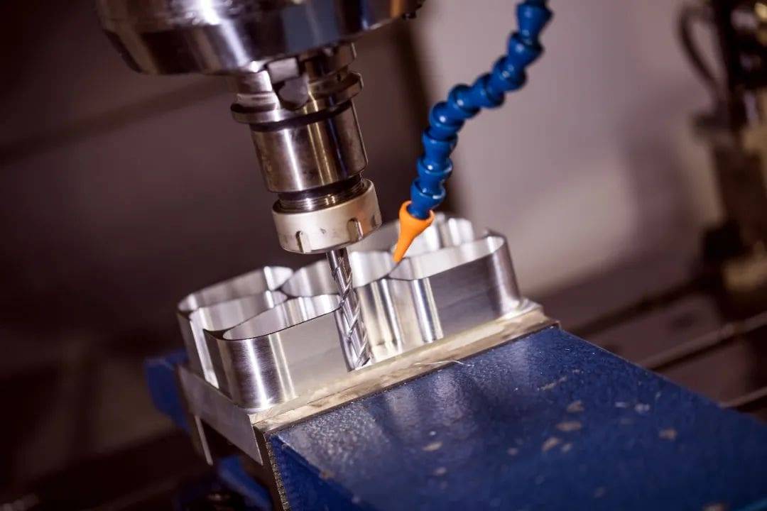
The core idea is simple: the easier a part is to machine, the lower its cost and the higher its quality. CNC machines remove material with rotating tools, so every feature must be reachable by a tool of appropriate size. If a feature is too deep, too small, or too sharp, it may require special tooling, extra setups, or even a different process altogether.
For example, sharp internal corners are difficult to produce because cutting tools are round. A square pocket with a sharp corner would require a smaller tool and multiple passes, increasing machining time and tool wear. Designers who understand this can add a small radius to internal corners and significantly reduce cost without affecting function.
Applying design for CNC machining principles early in the product development cycle helps you avoid expensive revisions later. It also makes your parts more attractive to suppliers, because they can quote confidently with fewer assumptions and less risk.
Core Design Rules for CNC Machining
The most important rules in design for CNC machining are based on how tools move and how material behaves during cutting. These rules apply to most CNC milling and turning operations and should be reviewed before you finalize any drawing.
1. Avoid Sharp Internal Corners
Internal corners should have a radius larger than the cutting tool radius. A common recommendation is 0.8 mm to 1.5 mm for standard milling tools. Smaller radii require smaller tools and slower machining, which raises cost.
2. Limit Deep Pockets and Cavities

Deep pockets require longer tools, which can deflect and cause vibration. A general rule is to keep pocket depth no more than four times the tool diameter. If deeper features are necessary, discuss them with your machinist early.
3. Design Reasonable Wall Thickness
Thin walls can vibrate during machining and may deform under cutting forces. For metal parts, a minimum wall thickness of 0.8 mm is often recommended, though this depends on the material and part size. For plastics, thicker walls are usually safer.
4. Use Standard Hole Sizes and Threads
Standard drill sizes and thread pitches are easier to machine and do not require custom tooling. Non-standard threads may require special taps or thread milling, which adds cost and lead time.
5. Avoid Undercuts When Possible
Undercuts require special tools or angled setups. They are not impossible to machine, but they add complexity. If an undercut is necessary, keep it shallow and accessible.
6. Add Generous Fillets Where Stress Matters
Fillets reduce stress concentration and improve part strength. They also help with tool path continuity, which can improve surface finish and reduce machining time.
These rules are not absolute. Every part is different, and some features are unavoidable. The key is to know when a rule matters and when it can be relaxed with the help of an experienced machining partner.
Material Selection and Its Impact on Design
Material choice affects not only part performance but also how easy the part is to machine. Softer materials like aluminum 6061 are easy to cut, produce good surface finishes, and are widely available. Stainless steel, titanium, and hardened alloys are stronger but harder to machine, which increases cycle time and tool wear.
When you select a material, consider three things: mechanical properties, machinability, and cost. A material that is perfect for your application may be unnecessarily expensive to machine if a more machinable alternative can meet the same requirements.
For example, aluminum is often chosen for prototypes and low-volume production because it machines quickly and allows for faster iteration. Steel is chosen for structural parts that need higher strength, but it may require slower cutting speeds and more rigid setups. Plastics such as Delrin or PEEK are used in applications where weight, friction, or chemical resistance matter, but they require sharp tools and controlled feeds to avoid melting.
Your material selection should be finalized before you send files for quotation. Changing material after machining begins can invalidate tolerances, surface treatments, and even the entire design. If you are unsure which material fits your application, ask your supplier for guidance based on your load, temperature, and environmental requirements.
Tolerances and Surface Finish
Tolerances specify how much a dimension may vary from the nominal value. They are essential for parts that must fit or function with other components. However, tighter tolerances require more machining time, more inspection, and sometimes additional setups.
A standard CNC machining tolerance is often ±0.1 mm for general features. Tighter tolerances like ±0.05 mm or ±0.02 mm are possible but should only be applied where functionally necessary. Over-specifying tolerances across the entire part is one of the most common reasons for unnecessarily high quotes.
Surface finish is another factor that affects cost. A standard machined finish may be around Ra 3.2 µm. If you need a smoother surface for sealing, sliding, or aesthetic reasons, you may request Ra 1.6 µm or lower. This requires finer tool passes and sometimes secondary operations like polishing.
When you specify tolerances and surface finish, be precise about which features matter. Mark critical dimensions on your drawing and leave the rest at standard values. This gives the machinist flexibility and keeps your cost under control.
Common Design Mistakes That Increase Cost
Many design issues are repeated across projects. Recognizing them early can save you time and money.
1. Over-Specified Tolerances
Applying tight tolerances to every dimension, even where not needed, increases inspection time and scrap risk. Only critical mating surfaces need tight tolerances.
2. Non-Standard Thread Depths
Threads that are too deep relative to their diameter require special tooling and longer machining time. Keep thread depth within standard ranges unless your application demands otherwise.
3. Unreachable Features
Features that are hidden behind walls or located deep inside a cavity may require custom tools or angled heads. If a feature cannot be reached by a standard tool, machining becomes significantly more complex.
4. Ignoring Tool Diameter
Designing slots or pockets smaller than common tool sizes forces the machinist to use smaller tools, which are weaker and slower. This increases cycle time and tool breakage risk.
5. Unnecessary Complex Geometry
Freeform curves and complex 3D surfaces look impressive but take much longer to machine than simple prismatic shapes. If a curved surface is not required for function, consider simplifying it.
6. Not Considering Part Orientation
The orientation of the part on the machine affects the number of setups required. A part that can be machined in one setup is cheaper than one that needs to be flipped and re-fixtured multiple times.
Avoiding these mistakes is not difficult if you review your design with manufacturing in mind. A quick internal review before sending files for quotation can prevent most of these issues.
How Design Choices Affect Machining Time
Machining time is the largest driver of CNC part cost. Every design decision that reduces machining time directly reduces your unit price. The most significant time factors are the number of tool changes, the depth of cuts, and the complexity of tool paths.
For example, a part with many different hole sizes requires multiple drill changes. Each tool change adds time and potential for error. Standardizing hole sizes across the part reduces tool changes and speeds up production.
Similarly, deep cavities require multiple passes with progressively longer tools. This increases cycle time and may require slower spindle speeds to avoid vibration. Shallow features can be machined in a single pass with a rigid tool, which is faster and more reliable.
Parts that require multiple setups also add time. Each setup involves repositioning the part, re-fixturing, and re-zeroing the machine. If your design can be machined from one side or with minimal reorientation, you will save time and reduce the chance of positional errors.
By focusing on machining time reduction through design choices, you can lower your total cost without compromising part quality. This is one of the most practical ways to make your project more economical.
Questions Buyers Often Ask About CNC Machining Design
How much does design for CNC machining affect the final price?
Design choices can change the price significantly. A part with simple geometry, standard tolerances, and common materials can cost much less than a similar part with deep pockets, tight tolerances, and custom threads. In many cases, simplifying the design reduces cost by 20% to 40% without affecting function.
What is the minimum wall thickness for CNC machined metal parts?
For most metals, a minimum wall thickness of 0.8 mm is safe, but this depends on the material and the height of the wall. Taller walls need to be thicker to avoid vibration during machining. For plastics, a minimum of 1.0 mm to 1.5 mm is often recommended.
Can I machine internal threads in CNC machining?
Yes, internal threads can be machined using taps or thread mills. Standard thread sizes are easier and cheaper to produce. Non-standard threads may require special tooling and should be discussed with your supplier before finalizing the design.
Should I use tight tolerances on all dimensions?
No. Tight tolerances should only be applied where parts must fit or align with other components. Over-specifying tolerances increases machining time, inspection cost, and the risk of parts being rejected. Use standard tolerances for non-critical features.
How can I reduce the cost of my CNC machined part?
You can reduce cost by simplifying geometry, standardizing hole sizes, avoiding deep cavities, and selecting a machinable material. Sending a clear drawing with properly specified tolerances also helps the supplier quote accurately and avoid assumptions.
Do I need to provide a 3D model for CNC machining?
A 3D model in STEP or IGES format is the most useful file type for CNC machining. It allows the machinist to program tool paths directly. A 2D drawing with critical dimensions and tolerances is also helpful, especially for inspection requirements.
What file format should I send for a CNC machining quote?
STEP files are widely accepted and preferred. Some suppliers also accept Parasolid or native CAD files. Always confirm the preferred format with your supplier before sending files.
Can design for CNC machining rules be applied to prototypes as well?
Yes, the same rules apply to prototypes and production parts. Applying these rules early helps you test the actual manufacturing process and avoid surprises when you scale up to higher volumes.
Choosing the Right CNC Machining Partner
Even with a well-designed part, the quality of your final product depends on the supplier you choose. A good CNC machining partner reviews your design, identifies potential manufacturing issues, and suggests improvements before production begins.
When evaluating a supplier, ask about their experience with your material, their inspection process, and how they handle tolerances. A supplier that provides engineering feedback during the quoting stage is more likely to deliver a part that meets your requirements without unnecessary cost.
YPMFG supports projects that require careful design review and manufacturing feedback. When you send your specifications, the engineering team reviews the geometry, flags potential machining issues, and suggests adjustments that can reduce cost or improve reliability. This kind of early collaboration helps you avoid expensive surprises later.
You can send your drawings and 3D models to YPMFG for a detailed review. The team can help you compare material options, confirm tolerances, and evaluate whether your current design is optimized for CNC machining. This is especially useful if you are new to CNC manufacturing or if your part has complex features.
Making a Better Long-Term Decision
Design for CNC machining is not a one-time checklist. It is a mindset that helps you create parts that are easier to produce, more consistent in quality, and more economical over the life of the product. The earlier you apply these principles, the more control you have over cost, lead time, and performance.
If you are preparing a new design or revising an existing one, take the time to review the geometry,material, and tolerances before sending files for quotation. Ask your supplier for feedback and be open to suggestions. A small change in the design phase can lead to significant savings in production.
When you are ready to move forward, send your specifications to YPMFG for engineering review and a competitive quote. The team can help you validate your design, recommend the most cost-effective manufacturing approach, and support you from prototype to production.