To fully leverage the capabilities of CNC machining, designers must follow specific manufacturing guidelines but that can be tricky, as no strict industry standards exist. This article compiles a complete guide to CNC machining design best practices.
We focus on the practical capabilities of modern CNC systems, leaving cost optimization for a separate discussion. For tips on designing cost-effective CNC parts, please refer to our related article.
Table of Contents
1. What Is CNC Machining?
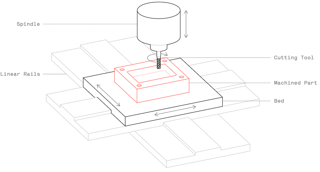
CNC machining is a subtractive manufacturing process. Using high-speed rotating tools (often thousands of RPM), material is removed from a solid block to produce parts according to CAD models. Both metals and plastics can be CNC machined.
CNC-machined parts offer high dimensional accuracy and tight tolerances, making the process suitable for both mass production and one-off projects. In fact, CNC machining remains one of the most cost-effective ways to produce metal prototypes — even compared to 3D printing.
2. Main Design Limitations of CNC
CNC machining offers great flexibility, but certain design constraints arise from the mechanics of the cutting process — mainly tool geometry and tool accessibility.
1. Tool Geometry
Common CNC tools (end mills and drills) are cylindrical and have limited cutting lengths. When material is removed, the tool shape is transferred onto the part, meaning that internal corners will always have a radius, no matter how small the tool.
2. Tool Accessibility
To remove material, the tool approaches the workpiece directly from above. Features that cannot be accessed this way cannot be CNC machined.
There is one exception to this rule: undercuts. We’ll learn how to use undercuts in design in a later section.
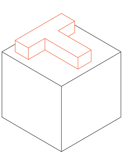
A good design practice is to align all features of a model (holes, cavities, vertical walls, etc.) with one of the six cardinal directions. Consider this rule as a suggestion, not a restriction, as 5-axis CNC systems offer advanced workholding capabilities.
Tool access can also be a problem when machining features with large aspect ratios. For example, reaching the bottom of a deep cavity requires specialized tools with long shafts. This reduces end-effector stiffness, increases vibration, and reduces achievable accuracy.
CNC experts recommend designing parts so that they can be machined using tools with the largest possible diameter and shortest possible length.
3. CNC Design Rules
There are no universal standards for CNC design machine capabilities vary. Below is a summary of recommended and achievable values for common part features.
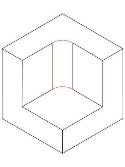
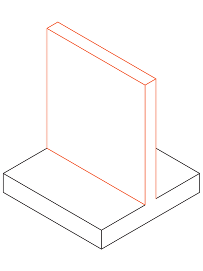
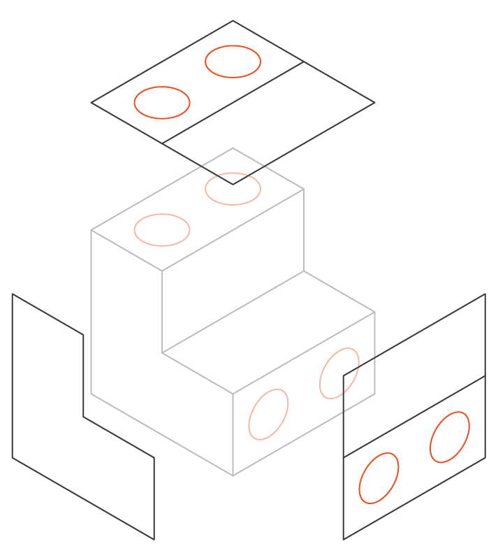
1. Cavities and Pockets
Recommended Cavity Depth: 4 Times the Cavity Width
End mills have a limited cutting length (typically 3-4 times their diameter). When the depth-to-width ratio is small, tool deflection, chip evacuation, and vibration become more pronounced. Limiting the cavity depth to 4 times its width ensures good results.
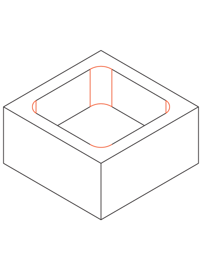
If greater depth is required, consider designing a part with variable cavity depth (see the image above for an example).
Deep cavity milling: A cavity is considered deep if its depth is greater than six times the tool diameter. Specialized tooling can achieve a tool diameter to cavity depth ratio of 30:1 (using a 1-inch diameter end mill, the maximum depth is 30 cm).
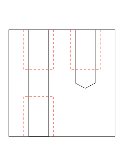
2. Internal Edges
- Corner radius: ≥ ⅓ × cavity depth (or larger)
Using the recommended internal corner radius ensures that the appropriate diameter tool can be used and aligns with the recommended pocket depth guidelines. Increasing the corner radius slightly above the recommended value (for example, by 1 mm) allows the tool to cut along a circular path rather than at a 90° angle. This is preferred because it produces a higher-quality surface finish. If a sharp 90° internal corner is required, consider adding a T-shaped undercut rather than reducing the corner radius.
Recommended floor radii are 0.5 mm, 1 mm, or no radius, any radius is acceptable.
The bottom edge of an end mill is either flat or slightly rounded. Other floor radii can be machined using a ballnose tool. Using the recommended value is good design practice, as it is the machinist’s preferred choice.
3. Thin Walls
- Recommended minimum thickness: 0.8 mm (metal), 1.5 mm (plastic)
- Achievable: 0.5 mm (metal), 1.0 mm (plastic)
Reducing the wall thickness reduces the stiffness of the material, which increases vibrations during processing and reduces the achievable accuracy. Plastics tend to warp (due to residual stresses) and soften (due to increased temperature), so a larger minimum wall thickness is recommended.
4. Holes
- Recommended diameter: Standard drill sizes (≥ 1 mm)
- Recommended max depth: 4× nominal diameter
- Typical: 10× nominal diameter
- Achievable: 40× nominal diameter
Drilled holes have conical bottoms (135°). Milled holes are flat-bottomed. There’s no preference between blind and through holes in CNC machining.
5. Threads
- Minimum thread size: M2
- Recommended: M6 or larger
- Minimum thread length: 1.5× nominal diameter
- Recommended: 3× nominal diameter
Threads are typically cut using taps (internal) or dies (external). For blind holes (below M6), leave an unthreaded section equal to 1.5× diameter at the bottom.
6. Small Features
- Recommended minimum hole diameter: 2.5 mm
- Achievable: 0.05 mm (micro-machining)
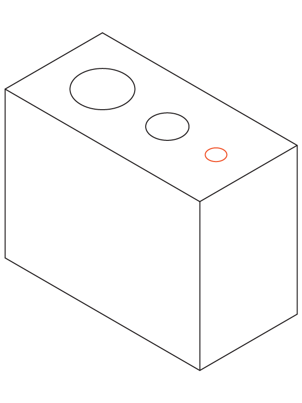
Features smaller than 2.5 mm require specialized micro-tools and expert knowledge, increasing cost and risk. Avoid unless necessary.
7. Tolerances
- Standard: ±0.125 mm (±0.005 in)
- Typical: ±0.025 mm (±0.001 in)
- Achievable: ±0.0125 mm (±0.0005 in)
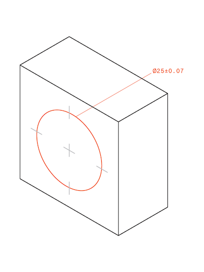
If not specified, most workshops use the standard ±0.125 mm. Tighter tolerances increase machining time and cost.
8. Text and Engravings
- Recommended font size: ≥ 20 pt
- Engraving depth: ~5 mm
Raised text (engraving) is preferred for efficiency. Use sans-serif fonts (e.g., Microsoft YaHei, Verdana) most CNCs support these.
4. Machine Setup and Orientation
Each additional setup (rotating or repositioning the part) increases cost and alignment error.
To maintain accuracy and efficiency:
- Minimize setups (3–4 is acceptable).
- Machine critical features in the same setup when possible.
5. 5-Axis CNC Machining
5-axis systems can approach the part from multiple angles, reducing setups and allowing complex geometries. They produce better surface finishes and shorter machining times though costs are higher.
However, limitations from tool geometry and accessibility still apply (e.g., internal cavities remain challenging).
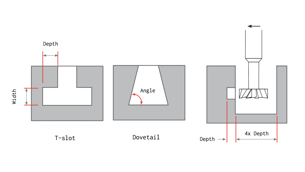
6. Designing for Undercuts
Undercuts are features that cannot be machined using standard cutting tools because some of their surfaces are inaccessible from above.
There are two main types of undercuts: T-slots and dovetails. Undercuts can be single-sided or double-sided and are machined using specialized tooling.
T-slot cutting tools essentially consist of a horizontal cutting insert attached to a vertical shaft. The width of an undercut can vary between 3 mm and 40 mm. It is recommended to use standard dimensions for width (i.e., whole millimeter increments or standard fractions of an inch) because the tools are more likely to be readily available.
For dovetail tools, the angle is the defining feature dimension. 45° and 60° dovetail tools are considered standard.
When designing parts with undercuts on internal walls, remember to add sufficient clearance for the tool. A good rule of thumb is to add space between the machined wall and any other internal walls equal to at least four times the depth of the undercut.
For standard tools, the typical ratio between the cutting diameter and the shaft diameter is 2:1, which limits the depth of cut. When non-standard undercuts are required, machine shops often fabricate custom undercut tools. This increases lead time and cost and should be avoided whenever possible.
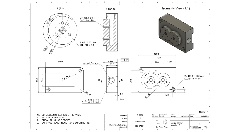
7. Technical Drawings & Communication
3D CAD files (STEP/IGES) don’t include all details. Provide 2D technical drawings when your design includes:
- Threaded holes or shafts
- Dimensional tolerances
- Specific surface finish requirements
Clear documentation prevents misunderstandings and rework.
8. Key Design Takeaways
- Design parts to use the largest, shortest tools possible.
- Add large internal radii (≥⅓ × cavity depth).
- Limit cavity depth to ≤ 4× its width.
- Align features to six principal directions or consider 5-axis CNC.
- Always include technical drawings for threads, tolerances, or finishes.
9. Conclusion
At YP-MFG, we combine years of CNC manufacturing expertise to provide end-to-end services from design optimization and rapid prototyping to mass production. Whether you’re improving part geometry or reducing machining costs, we help turn your drawings into precision-engineered reality.