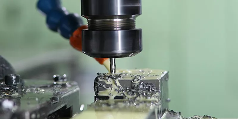
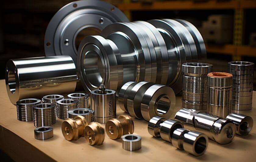
CNC machining polycarbonate (PC) requires a specific approach to avoid cracking, stress whitening, and poor surface finish. When done correctly,it produces durable, optically clear components for applications like protective shields, medical devices, and automotive parts. Below are seven proven guidelines based on real shop-floor practices.
1. Use sharp, polished carbide tools
Polycarbonate is relatively soft but prone to melting and chipping. Standard high-speed steel (HSS) tools dull quickly, generating excess heat. A common case: A job shop machining PC camera housings switched from HSS end mills to single-flute, polished carbide tools. Tool life tripled, and edge burrs disappeared. Always use tools with a 10°–15° positive rake angle and a polished flute surface to minimize friction.
2. Maintain proper feed and speed
Typical starting parameters for CNC milling polycarbonate:
Spindle speed: 12,000–18,000 RPM
Feed rate: 50–80 IPM (inches per minute) for 1/8″ tool
Depth of cut: ≤0.020″ per pass for thin walls; up to 0.060″ for bulk removal
For drilling: use parabolic flute drills at 3,000–6,000 RPM, pecking every 0.030″. A prototype shop reported that reducing spindle speed from 24,000 to 15,000 RPM eliminated melt-back welding inside blind holes.
3. Control heat with coolant or compressed air
Polycarbonate softens at ~300°F (149°C). Even brief overheating causes smearing and dimensional loss. Use high-pressure air blast (80–100 PSI) for most operations – mist coolant is acceptable but ensure water-based coolant is fully evaporating; trapped moisture can cause stress cracking later. For deep pockets, flood coolant with a 10% soluble oil emulsion works well, but parts must be dried immediately.
4. Secure workholding without over-clamping
PC parts distort easily under clamping pressure. A manufacturer of clear machine guards learned this when 5% of parts cracked within 24 hours of removal. Solution: soft jaws with full-contact padding (neoprene or 60A polyurethane), torqued to only 5–8 in-lbs. For thin sheets (≤0.125″), use vacuum tables or double-sided tape with a low-tack acrylic adhesive.
5. Design for stress-free machining
Avoid sharp internal corners – use a minimum radius of 0.030″. A medical device company eliminated field failures of PC fluid connectors by changing all 90° internal corners to 0.060″ radius. Also, never machine across a pre-existing stress line (e.g., near laser-cut edges). Always rough first, then finish with a light pass (≤0.010″ stock removal) to relieve residual stresses.
6. Anneal post-machining for stability
Even with perfect parameters, machined PC retains surface stresses. To prevent environmental stress cracking (from contact with alcohol, oils, or cleaning agents), anneal parts at 250°F (121°C) for 1 hour per 0.250″ thickness, then slow cool to room temperature. A sign maker who skipped annealing saw 30% of outdoor illuminated letters crack in winter; after adopting this cycle, failures dropped to near zero.
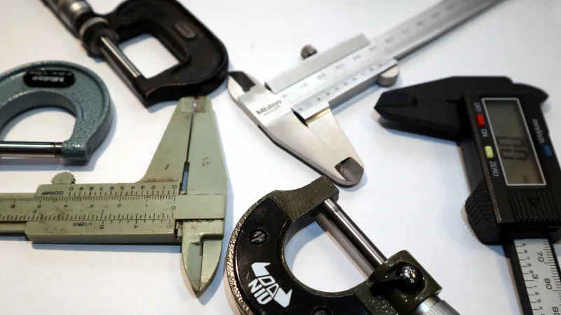
7. Inspect using cross-polarized light
After machining, examine parts between two polarizing filters. Visible rainbow patterns indicate residual stress. No pattern means low stress – ready for use. This non-destructive test takes seconds and saves costly rework.
Reinforce the core takeaway
Successful CNC polycarbonate machining centers on three pillars: sharp tools, low heat, and stress management. Every parameter adjustment – from feed rates to clamping pressure – serves these goals.
Action steps for your next PC job
1. Order one extra sheet for test cuts to dial in feeds/speeds.
2. Create a setup card: tool type, RPM, IPM, coolant method, and clamping torque.
3. After first part, inspect for melt marks and stress patterns before running the full batch.
Implement these seven tips, and you will produce polycarbonate parts that are dimensionally accurate, optically clear, and free from hidden cracks – ready for the most demanding applications.