Quick answer:
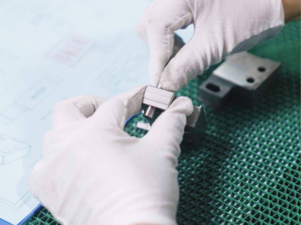
A CNC milling prototype is a functional, machined part produced directly from a CAD model using subtractive manufacturing, typically before moving to production tooling. It is used to verify fit, function, material behavior, and assembly tolerances before committing to higher-volume manufacturing. For most mechanical components, CNC milling is the fastest and most reliable way to produce a single or low-volume part with production-grade material properties and surface finish. The key advantages are speed, accuracy, material choice, and the ability to iterate without hard tooling costs.
Prototyping with CNC milling is not ideal for every scenario. If you need dozens of parts with complex internal geometries or extremely low per-unit cost, alternatives like 3D printing or casting may be more appropriate. However, when dimensional accuracy, mechanical strength, and surface finish are critical, CNC machining is the standard choice. Understanding where it fits in your development cycle—and what to expect in terms of cost and timeline—can save both engineering hours and project budget.
Why Choose CNC Milling for Prototyping
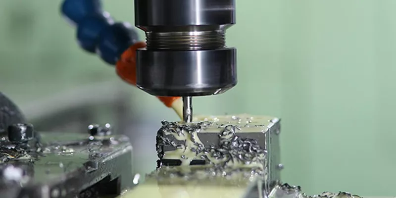
CNC milling is subtractive manufacturing at its most precise. A solid block of material is clamped on a machine bed, and a rotating cutting tool removes material according to a programmed path. For a prototype part, this process offers two major advantages: material fidelity and dimensional accuracy.
Because the part is cut from a solid block, the mechanical properties match the final production material. If your production part will be machined from 6061 aluminum or 304 stainless steel, the prototype will behave identically under load, temperature, and wear. This is critical for functional testing, especially in aerospace, medical devices, and automotive applications.
Dimensional tolerances for CNC milled prototypes typically range from ±0.005 in. to ±0.001 in., depending on geometry and machine capability. This level of precision allows engineers to validate fits, verify critical interfaces, and catch interference issues before tooling is cut for production.
Typical Lead Time for CNC Milled Prototypes
Lead time for a CNC milling prototype depends on complexity, material availability, and the machine shop’s current workload. Standard turnaround for a simple 2-axis or 3-axis part can be as fast as 2–5 business days. More complex parts requiring 5-axis machining, tight tolerances, or exotic materials may take 1–3 weeks.
Most professional machine shops prioritize prototype work because it often leads to production orders. Shops that offer rapid prototyping services typically keep common materials like aluminum, steel, and engineering plastics in stock. Requesting a lead time estimate early in your design phase helps align delivery with your project milestones.
When comparing vendors, ask about their typical prototype throughput and whether they offer expedited services. A few days of lead time can make a significant difference when you are racing toward a design freeze or customer demo.
Cost Factors for CNC Milling Prototype Parts
The cost of a single CNC milled prototype is driven by several variables. Understanding these factors helps you control budget without sacrificing quality.
The most effective way to reduce prototype cost is to simplify geometry where possible. Eliminating unnecessary deep pockets, small internal radii, or tight tolerances on non-critical surfaces can cut machining time by 30% or more.
For budget-sensitive projects, YPMFG can review your CAD model and suggest design modifications that maintain function while reducing machining steps. This kind of early engineering feedback often pays for itself in faster turnaround and lower per-part cost.
Materials Commonly Used in Prototype Machining
Material selection for a CNC milling prototype should mirror the production material whenever possible. If the production part is cast or forged, a machined prototype in the same alloy still provides valid mechanical test data.
Common prototype materials include:
Aluminum 6061-T6 – Excellent machinability, good strength, low cost. The most common choice for general prototypes.
Aluminum 7075-T6 – Higher strength, often used in aerospace and high-stress applications.
304 Stainless Steel – Corrosion resistant, good weldability. Common in medical, food, and marine prototypes.
316 Stainless Steel – Better corrosion resistance than 304. Used for saltwater or chemical environments.
Mild Steel (1018, 1215) – Low cost, easy to machine. Suitable for structural prototypes.
ABS, Delrin (POM), Nylon – Engineering plastics for lightweight, low-friction, or dielectric prototypes.
Brass, Copper, Bronze – Used for electrical, plumbing, or decorative prototypes.
If your production material is difficult to machine (e.g., titanium, Inconel), consider whether a prototype in 6061 aluminum can provide adequate functional data at a fraction of the cost. Many engineers use this strategy for early design validation.
CNC Milling Prototype vs. 3D Printing: When to Use Each
Both CNC milling and 3D printing are used for prototyping, but they serve different needs. Choosing the wrong process can delay your project or inflate costs.
Use CNC milling when the prototype must survive actual operating conditions. Use 3D printing when you need a quick visual check or a complex internal geometry that cannot be machined. Many product development cycles use both: a 3D-printed form study first, then a CNC milled prototype for final functional validation.
Design Considerations for Prototype Machining
To get the most value from your CNC milled prototype, consider these design guidelines early in the CAD phase.
Avoid deep, narrow pockets. A pocket deeper than 4x the tool diameter requires specialized tooling and slower feed rates. Split the feature into shallower sections if possible.
Use standard radii. Sharp internal corners require small tools and slow machining. A radius of 0.030 in. or 0.060 in. is standard and reduces cost.
Minimize tight tolerances. Only call out tight tolerances on features that directly affect function. Over-specifying tolerances on every dimension adds inspection time and cost without benefit.
Consider thin walls. Walls thinner than 0.020 in. in metal or 0.040 in. in plastic can chatter or distort during machining. Increase wall thickness for prototype runs to ensure successful machining.
Include a datums and reference surfaces. This helps the machinist set up the part accurately and reduces the chance of errors in critical dimensions.
If you are unsure how your design will machine, YPMFG offers an engineering review of your CAD files before quoting. This step catches potential issues early and often results in a lower quote and faster delivery.
Questions Buyers Often Ask About CNC Milling Prototypes
How much does a single CNC milled prototype cost?
For a simple aluminum part with standard tolerances, expect $50–$150. Complex parts with tight tolerances, multiple setups, or exotic materials can range from $300 to $1,000 or more. Always request a quote with your CAD file for an accurate estimate.
What is the fastest lead time for a CNC milled prototype?
Many shops can deliver a simple prototype in 2–5 business days with standard service. Expedited orders, sometimes called rush prototyping, can be completed in 24–48 hours for an additional fee. Check with your machine shop about availability.
Can I use the same CNC program for prototypes and production?
Often yes, but not always. A prototype may use different tooling or feed rates than a high-volume production run. However, the same CAM program can usually be optimized for production after prototype validation.
Do I need a technical drawing for a prototype?
A 3D CAD file is often sufficient for a prototype quote. However, a detailed 2D drawing with tolerances, surface finish requirements, and critical dimensions reduces the risk of miscommunication. Most machine shops prefer both.
What surface finish is standard for CNC milled prototypes?
The as-machined finish is standard, typically 63–125 Ra microinches. If you need a smoother finish, specify it on your drawing. Post-processing options like bead blasting, anodizing, or polishing are available upon request.
How many prototypes should I order?
For fit and function validation, one or two parts are often enough. If you need multiple assemblies or want to run destructive tests, ordering 5–10 parts spreads the setup cost and gives you backup parts for testing.
Can CNC milling produce internal threads or tapped holes?
Yes. Threaded holes are common in CNC milled prototypes. Specify thread size, depth, and class on your drawing. For deeper threads, thread milling or helical interpolation can be used for better quality.
What file formats do machine shops accept?
Most shops accept STEP, IGES, or Parasolid 3D files. Some also accept native SolidWorks, Fusion 360, or NX files. Always confirm the preferred format with your vendor before sending files.
Need Help With Your CNC Milling Prototype?
Getting a CNC milling prototype right the first time requires more than just sending a CAD file. It means understanding material behavior, machining limitations, and cost drivers from the start. Whether you are validating a single part for a design review or preparing for a small pre-production run, the right partner can help you avoid common pitfalls.
YPMFG supports prototype projects across a wide range of industries, including aerospace, medical, automotive, and industrial equipment. You can send your CAD file and specifications for an engineering review and quote. The team can advise on material selection, tolerance strategy, and surface finish options—all before a single toolpath is cut. If you are comparing CNC machining services, requesting a quote for your prototype is a low-risk way to evaluate capability and communication speed.
Making the right decisions during prototyping leads to faster product launches, fewer design iterations, and lower overall project risk.


