In today’s era of explosive growth in the new energy vehicle (NEV) market, electric motors have become the “heart” driving future mobility. As two core structural components of electric motors, the machining quality of motor housings and motor shafts directly determines the motor’s operational precision, vibration noise levels, and service life.
For vehicle manufacturers pursuing high performance, lightweight design, and efficiency, procurement standards for core motor components are exceptionally stringent. We recognize that the current supply chain faces significant challenges: traditional machining processes yield a combined scrap rate as high as 12% and impose production capacity constraints.
Drawing upon extensive engineering expertise and specialized CNC machining technology, this paper systematically analyzes the machining challenges of new energy vehicle motor housings (aluminum alloy) and motor shafts (alloy steel). It proposes a comprehensive solution encompassing process optimization, equipment selection, fixture design, and intelligent manufacturing. This article serves not only as a technical report but also as a reliable, replicable high-precision manufacturing system to support your procurement decisions and engineering optimization.
I. New Energy Motor Housings
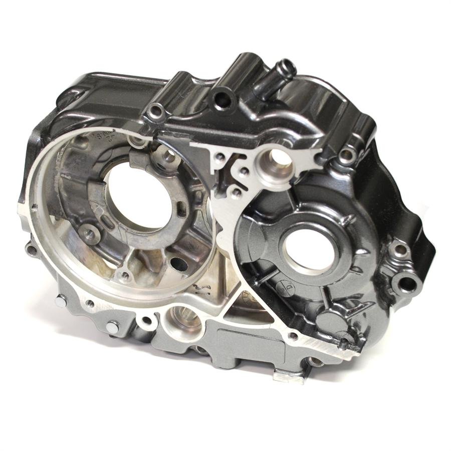
1.1 Analysis of Material and Structural Characteristics of Motor Housings
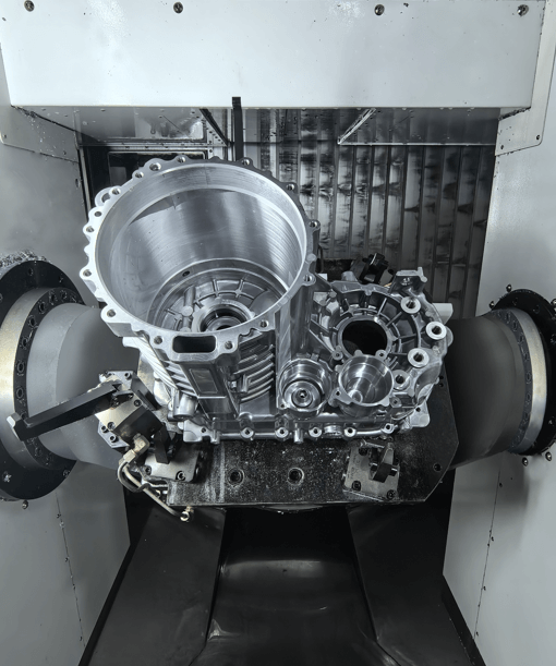
New energy vehicle motor housings commonly utilize aluminum alloys such as 6061-T6 to achieve lightweight objectives (reducing mass by 40% compared to cast iron housings). However, the material properties and thin-walled cylindrical structure (wall thickness 3–5 mm, aspect ratio 1:1) present three core challenges for CNC machining:
| Feature | Technical Challenges | Critical Accuracy Requirements |
|---|---|---|
| Thin-Walled Structure | Deformation control: insufficient overall rigidity leads to vibration and deformation during machining. In traditional 3-axis machining, cumulative spring-back error from multiple passes can reach 0.08 mm. | Bearing bore coaxiality must be ≤ 0.02 mm. |
| High Thermal Expansion | Thermal deformation: aluminum alloys have high thermal conductivity and large thermal expansion. When cutting temperature exceeds 100°C, a 60 mm bearing bore may expand radially by up to 0.027 mm. | Critical surfaces require flatness < 0.03 mm. |
| Complex Cavities | Multi-axis coordination & coaxiality: including dual high-precision bearing bores and cooling fins with a height-to-width ratio of 3:1. Repeated clamping in traditional processes leads to accumulated positioning errors. | Bearing bore surface roughness Ra ≤ 1.6 µm. |
1.2 Solution: High-Precision Composite Machining Process Chain for Motor Housings
We employ a composite process chain integrating die-casting precision control, five-axis layered milling, and precision turning with reference correction to systematically address the aforementioned challenges:
(1) Front-end Process Chain Optimization: Precision Control in Die-Casting
By precisely controlling mold temperature and achieving rapid filling, combined with bridge structure design, the blank allowance is consistently maintained at 0.3mm. This measure reduces porosity defects by 60%, providing high-precision blanks for subsequent machining.
(2) Thin-Wall Deformation Control: Five-Axis Layered Milling
• Strategy: Employing a five-axis machining center for layered processing. During finishing, a 20°C tool inclination is used for climb milling. This tool orientation adjustment effectively reduces cutting forces by 25% and minimizes thermal deformation by 0.015mm.
• Temperature Control: Finishing employs minimal depth of cut (≤0.3mm) with real-time workpiece temperature monitoring. Infrared thermometry maintains temperature rise below 50°C to minimize thermal deformation.
(3) Coaxiality Assurance: Precision Turning Benchmark Correction
In the final process, a high-precision CNC lathe with hydraulic soft chucks is used to precision-turn the bearing bore to H7 tolerance, controlling roundness within 0.015mm. This precision turning corrects cumulative errors from die casting and milling, ensuring both bearing bores meet coaxiality requirements.
II. New Energy Motor Shafts
2.1 Analysis of Motor Shaft Materials and Structural Characteristics
Motor shafts commonly utilize 40Cr or 20CrMnTi alloy steel, featuring high tensile strength (exceeding 785 MPa). Their typical configuration involves a slender stepped shaft structure with total lengths ranging from 500 to 800 mm, where the length-to-diameter ratio typically exceeds 10.
| Feature | Technical Challenges | Critical Accuracy Requirements |
|---|---|---|
| High Slenderness Ratio | Vibration and bending: A large length-to-diameter ratio results in weak rigidity, making turning and grinding prone to vibration. Uneven clamping force (difference of 200 N) increases deformation, causing roundness error up to 0.06 mm. | Bearing journal roundness must be ≤ 0.01 mm. |
| High-Precision Fit Surfaces | Grinding burn & surface quality: 40Cr alloy steel has low thermal conductivity, causing heat concentration. When wheel speed is too high, surface temperature may reach 800°C, leading to temper softening and grinding cracks. | Bearing journal surface roughness must be Ra ≤ 0.8 µm. |
| Dynamic Balance | Multi-error coupling & residual unbalance: Roundness error on bearing seats, deep-hole eccentricity, and keyway positional deviation collectively cause residual unbalance up to 12 kg·mm. | Dynamic balance must meet G2.5 grade (residual unbalance ≤ 2.5 kg·mm). |
2.2 Solution: Integrated “Turning-Grinding-Dynamic Balancing” Process for Motor Shafts
We established an integrated process system featuring “rigid-supported turning-precision grinding-closed-loop dynamic balancing” to ensure rotational accuracy and dynamic stability:
(1) Rigid-Supported Turning: Eliminates vibration in slender shafts
• Support Innovation: During turning, a 50N axial thrust support counteracts radial deformation. This composite support structure effectively neutralizes bending vibrations, improving journal roundness from 0.06mm to 0.015mm.
(2) Precision Grinding with Thermal Control: Achieving Mirror-Like Surfaces
• Equipment and Tools: Grinding employs a grinding machine paired with CBN wheels. CBN wheels achieve 3 times higher grinding efficiency than conventional wheels.
• Green Lubrication: Combining minimal lubrication technology (low cutting fluid consumption) achieves bearing seat roundness ≤0.01mm and surface roughness Ra ≤0.8µm at mirror-like precision, completely eliminating grinding burn risks.
(3) Dynamic Balance Closed-Loop Control: Meets G2.5 Grade
• Deep Hole Precision: Central deep holes (length-to-diameter ratio 20) are machined using a BTA high-pressure system (3MPa pressure), controlling straightness to 0.05mm/100mm to ensure precise balance counterweight accuracy.
• Closed-loop correction: Dynamic balancing tests are conducted after finishing. Residual unbalance is stabilized at ≤2.5 kg by removing excess material (milling or drilling) from flange ends or shaft shoulders or adjusting counterweights.
III. Integrated Solutions for Enhancing Core Manufacturing Competitiveness
Achieving high-precision, high-efficiency machining requires seamless collaboration across equipment, clamping systems, and intelligent processes.
3.1 Precision Matching of Equipment and Tools
We adhere to the equipment selection principles of “high-precision positioning, thermal deformation compensation, and minimized clamping integration”:
• Specialized Motor Housing Equipment: Utilize a five-axis machining center with five-axis positioning accuracy of ±0.005mm, equipped with a thermal compensation system to correct errors caused by temperature fluctuations in real time.
• Motor shaft precision machining equipment: Utilize high-precision CNC lathes (spindle radial runout ≤0.003mm) and grinding machines to form an “integrated turning-grinding” unit, controlling bearing seat roundness to ≤0.01mm.
• Tooling Innovations:
o Aluminum Alloy: Utilizes 10mm AlCrN-coated end mills to effectively suppress chatter on heat dissipation groove walls, stabilizing surface roughness Ra values at ≤3.2μm.
o Alloy Steel: Employs CBN-coated turning tools/grinding wheels, reducing wear rates by 40% during high-speed cutting while achieving mirror-finish machining without burn risk.
3.2 Innovative Optimization of Clamping Systems
Clamping deformation is a critical factor affecting the precision of thin-walled components and slender shafts.
• Motor Housing: Vacuum-Suction Flexible Clamping Solution
o Primary Support: Utilizes a ring-shaped vacuum suction cup that applies uniform suction pressure to the workpiece base, replacing traditional single-point clamping plates. This solution significantly reduces clamping deformation from 0.04mm to 0.01mm.
o Auxiliary Support: Adjustable nylon support blocks are added for overhanging areas. The combination of “vacuum suction primary positioning + flexible support assistance” reduces vibration deformation during side wall milling.
• Motor Shaft: Hydraulic Soft Grippers + Axial Support Rigid Clamping Solution
o Clamping Optimization: Hydraulic soft jaws dynamically balance clamping force, reducing force variance from 200N to 120N (40% improvement in uniformity).
o Rigidity Enhancement: A 50N axial thrust support device forms a composite structure with hydraulic soft jaws, effectively counteracting bending vibration. Amplitude reduced from 0.03mm to 0.01mm.
3.3 Intelligent Machining Solutions
Driving data-driven transformation in machining processes through AI technology, digital twins, and intelligent management systems (MES).
• AI Thermal Compensation Technology: During five-axis machining of motor housings, the CNC system employs AI to learn thermal deformation patterns in real time. By integrating temperature rise and machining duration, it dynamically predicts deformation. Measured compensation accuracy reaches 0.002mm, effectively suppressing thermal deformation in aluminum alloys.
• Digital Twin Prediction for Motor Shaft Grinding: Constructs a grinding digital twin model for processing risk prediction. Through thermal field simulation, the maximum temperature in the grinding zone is controlled below 400°C, preventing hardness reduction and grinding burn in alloy steel caused by high temperatures.
• Intelligent Manufacturing Execution System (MES): Enables refined control over the coordinated machining of two part categories.
o Parameter Adaptation: The system automatically retrieves optimal machining parameters based on part material (aluminum alloy or alloy steel), preventing parameter mismatches during mixed-line production.
o Tool Condition Prediction: Based on cutting force monitoring, the system automatically alerts for tool replacement when tool rake face wear reaches 0.1mm, enhancing tool utilization.
IV. Continuous Innovation for High-Performance Motors
To address the evolving demands for greater efficiency, lighter weight, and smarter functionality in motors for new energy vehicles, we have focused our research on breakthroughs in next-generation technologies:
1. Deep Integration of Digital Twin Technology Across the Entire Process: Establishing a digital twin model covering the entire manufacturing workflow. This system can predict chatter risks 30 seconds in advance and automatically adjust process parameters, projected to elevate the first-pass yield rate for critical precision metrics to over 99%.
2. Breakthroughs in Processing Technologies for New Lightweight High-Strength Materials: Researching machining techniques for magnesium alloys and carbon fiber reinforced plastics (CFRP). The goal is to control deformation of thin-walled magnesium alloy components (wall thickness 2–3 mm) within 0.02 mm and resolve challenges such as delamination during CFRP drilling.
3. Engineering Application of Green, Low-Carbon Machining Processes: Focusing on dry cutting, cryogenic machining (using liquid nitrogen cooling), and minimal lubrication techniques. For instance, cryogenic machining rapidly lowers workpiece surface temperatures below 50°C, preventing grinding burn while reducing coolant consumption by over 90%.
4. Integrated Development of Intelligent Machining Units: Combining AI algorithms, digital twin models, and IoT technology to develop integrated units for machining, inspection, and decision-making. This enables full-process adaptive control (e.g., tool wear self-compensation, thermal deformation self-correction).
Precision machining of motor housings and shafts represents a high-tech barrier in the new energy vehicle manufacturing supply chain. Through synergistic optimization and intelligent integration of materials, structures, and processes, we have successfully overcome bottlenecks in multi-source deformation, dynamic balancing, and efficiency enhancement:
• Motor housing: Coaxiality stably controlled within 0.02mm.
• Motor shaft: Bearing bore roundness consistently controlled within 0.01mm, achieving dynamic balance accuracy of G2.5 grade.
We deliver not just machining services, but a proven, highly reliable, and professional systematic manufacturing solution. This empowers buyers and engineers to consistently obtain high-quality, efficient, and traceable core motor components.
Contact Us
Is your project facing challenges with thin-walled deformation in motor housings or dynamic balancing control for motor shafts?
We offer proven solutions and advanced five-axis/integrated turning-grinding equipment, providing customized process design and stable batch supply capabilities.
Please reach out to our engineering team to further discuss your specific procurement requirements and technical specifications.
References: Fu Weiming. Challenges and Solutions in CNC Machining of Motor Housings and Shafts for New Energy Vehicles. Metal Processing (Cold Processing), 2025, (8): 1-7.