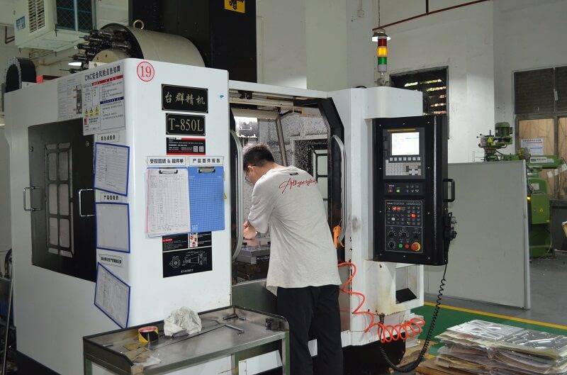
When machining large parts on CNC equipment, the real challenge is often not the cutting itself, but controlling deflection, thermal growth, and fixturing stability. As part size increases, material stress, machine travel, fixture support, and measurement error all become more obvious. If one of these factors is ignored, the result can be dimensional drift, rework, or scrap.
This guide focuses on the most common failure points in large-part CNC machining, including how to reduce tool deflection, manage thermal movement, improve fixture rigidity, and inspect the part before and after machining. At YPMFG, large-part projects are usually reviewed for support method, machining sequence, and critical dimension locations before production to reduce the risk of uncontrolled distortion.
Real‑world example: A manufacturer producing a 2‑meter aluminum aerospace bulkhead repeatedly encountered chatter and out‑of‑tolerance hole positions. After switching to modular fixturing with multiple support points and adopting high‑efficiency dynamic toolpaths, cycle time dropped by 22% and part rejection fell below 1%. This is not an isolated case—similar improvements are documented across heavy equipment, mold & die, and wind energy industries.
01Machine Selection – Rigidity Over Spindle Power
Large parts require machines that resist deflection under cutting forces. Minimum requirements:
Dual‑column or bridge‑type structure (gantry or plano mill)
Work envelope at least 20% larger than the part in X, Y, and Z axes
Box‑way construction on heavy axes (not linear guides for roughing)
Spindle taper HSK‑100 or CAT50+ for large‑diameter tools
Standard reference: According to ISO 230‑1 (machine tool geometry tests), a machine’s static stiffness should exceed 50 N/µm for reliable large‑part finishing.
02Workholding – The Most Overlooked Failure Point
Many large‑part errors originate from inadequate restraint. Follow these rules:
Support every 300‑400 mm – Use screw jacks, modular risers, or custom sub‑plates to prevent sagging (deflection under gravity).

Clamp direction – Apply clamping force toward solid machine elements (table or angle plates), not toward unsupported spans.
Low‑profile hydraulic or torque‑limiting clamps avoid distorting thin‑walled sections.
Verify contact with feeler gauges (0.05 mm max gap) before first cut.
Case: An automotive die shop machining a 1.8 m × 1.2 m cast iron die block reduced distortion by 73% after adding six adjustable support posts under the center of the part—eliminating a previously hidden 0.3 mm bow.
03Toolpath Strategies – Reduce Cutting Forces, Not Feed Rates
Large parts magnify the effect of radial engagement and tool overhang.
Trochoidal milling / dynamic toolpaths – Keep radial engagement ≤10% of tool diameter while maintaining high axial depth. This reduces cutting forces by up to 70% compared to conventional slotting.
Avoid full‑width slotting – Use ramp or helical entry where possible.
Tool overhang – Limit to ≤4× tool diameter for steel, ≤6× for aluminum. Use shrink‑fit or hydraulic chucks (not side‑lock holders) for better rigidity.
Z‑level finishing with constant stepover – Prevents scallop marks on tall walls.
Result from a heavy equipment manufacturer: Switching from conventional to adaptive clearing on a 1.5 m excavator arm reduced machining time from 14 to 9 hours and eliminated a secondary hand‑finishing step.
04Thermal Management – Every Degree Matters
A 1.8 m aluminum part grows approximately 0.02 mm per 10°C temperature rise. Over a 3‑hour cycle, shop temperature drift of 5°C can cause 0.01 mm error—enough to scrap a precision bore.
Run a coolant chiller – Maintain coolant within ±2°C of the shop’s baseline temperature.
Warm up the spindle – Perform a 15‑minute warm‑up cycle with spindle and axis motion before critical cuts.
Use thermal compensation if available on the CNC control (e.g., Heidenhain TNC’s active thermal compensation, but no brand names—check your machine manual).
For very large parts (4+ meters) , consider cutting in a climate‑controlled enclosure or scheduling roughing and finishing in separate temperature‑stable shifts.
Industry practice: ASME B89.6.2 (temperature and humidity for dimensional measurement) recommends maintaining 20°C ±1°C for final inspection of parts with tolerances ≤0.05 mm.
05Inspection – On‑Machine Probing Before Unclamping
Never trust that a large part stays in the same position after unclamping. Residual stress release often causes spring‑back.
Use a spindle probe to measure critical features while the part is still clamped.
Measure at three stages:
1. After roughing (check for distortion)
2. After semi‑finishing (verify stock remaining)
3. After finishing (confirm dimensions)
For parts with tight tolerances (≤ ±0.025 mm) , perform a final CMM inspection after stress relief (e.g., thermal cycling or vibratory stress relief).
Common failure avoided: A wind turbine hub manufacturer once scrapped five 900 kg castings because post‑unclamp spring‑back caused a 0.4 mm misalignment on bolt circles. Implementing on‑machine probing before unclamping caught the issue immediately, saving $45,000 per part.
06Core Principles – Repeat for Success
Rigid setup → more support points than you think you need.
Low cutting forces → dynamic toolpaths, not heavy cuts.
Thermal stability → control coolant and ambient temperature.
Inspect while clamped → never assume the part stays put.
07Actionable Next Steps
- Start by auditing your current large-part CNC machining process with a simple checklist: machine stiffness, workholding support spacing, toolpath type, coolant temperature control, and on-machine probing frequency. For large parts, the program may be correct, but poor support or thermal drift can still ruin accuracy.
- Upgrade workholding first. Adding modular supports, adjustable supports, or screw jacks often brings more improvement than changing tools. In many shop-floor cases, tolerance problems on large parts come from weak support or uneven clamping force.
- For parts longer than 1 meter, use adaptive clearing toolpaths for roughing. Whether your CAM software calls it dynamic milling, iMachining, or VoluMill, the goal is the same: keep tool load stable, reduce vibration, and limit part deflection.
- Track thermal drift during long cycles. Measure a reference feature every 30 minutes. If movement exceeds 0.02 mm, review coolant temperature, machine warm-up, or machining sequence.
These steps can turn large-part CNC machining from a risky process into a more repeatable and accurate workflow. At YPMFG, large-part jobs are also reviewed around fixturing, support, thermal control, and inspection frequency, because these basics often decide whether the final dimensions stay stable.