Threads are one of the most common structures in mechanical connections. This article systematically explains the basics of threads, including their classification, elements, marking methods, drawing techniques, and a common comparison table.
Table of Contents
1. Thread Types
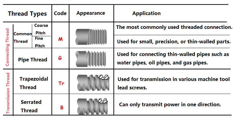
By thread profile: triangular, trapezoidal, rectangular, serrated, and circular.
By direction of rotation: left-hand and right-hand.
By number of threads: single-thread and multi-thread.
By parent body shape: cylindrical and conical.
2. Elements of a Thread
A thread consists of five elements: thread form, nominal diameter, number of threads, pitch (or lead), and direction of rotation.
1. Thread Profile
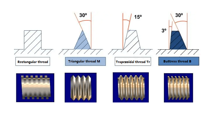
The thread’s profile, as measured in a cross-section through the thread axis, is called the thread profile. Profiles include triangular, trapezoidal, serrated, circular, and rectangular.
Comparison of thread profiles:
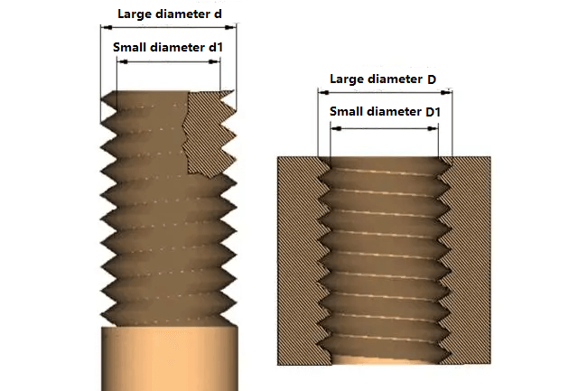
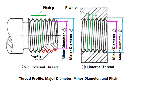
2. Diameter
Threads have a major diameter (d, D), a pitch diameter (d2, D2), and a minor diameter (d1, D1). Threads are designated by their nominal diameter, which represents the thread size.
The nominal diameter of a standard thread is the major diameter.
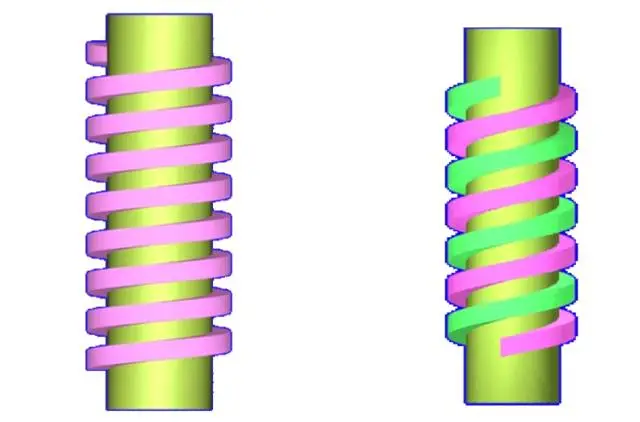
3. Number of Threads
A thread formed along a single helical line is called a single-start thread, while a thread formed by two or more helical lines equidistantly spaced along the axial direction is called a multi-start thread.
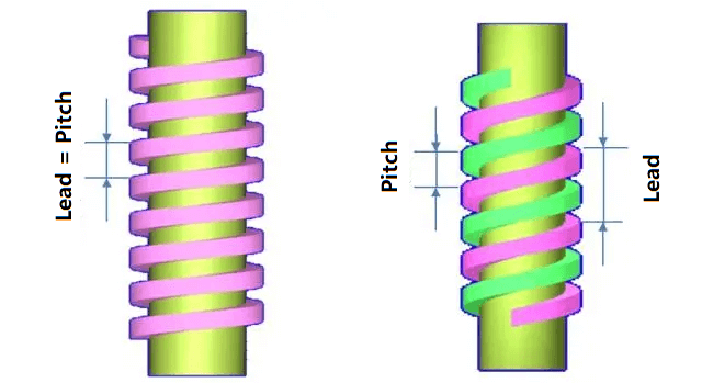
4. Pitch and Lead
Pitch (p) is the axial distance between two adjacent threads on the mid-diameter line.
Lead (ph) is the axial distance between two adjacent threads on the same helical line on the mid-diameter line.
For single-start threads, lead = pitch, for multi-start threads, lead = pitch × number of threads.
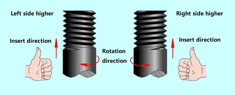
5. Direction of Thread
A thread that is screwed in clockwise is called a right-hand thread, a thread that is screwed in counterclockwise is called a left-hand thread.
3. Thread Marking
(1) Ordinary thread
Ordinary thread is the most widely used. The threads on threaded fasteners (bolts, studs, screws and nuts, etc.) are generally ordinary threads.
Ordinary threads are divided into coarse thread ordinary threads and fine thread ordinary threads. Fine thread ordinary threads are mostly used on precision parts and thin-walled parts.
In the thread marking, the pitch of fine thread ordinary threads must be noted, while the pitch of coarse thread ordinary threads is generally not marked.
The marking of ordinary threads consists of five parts:

1) Characteristic Code
M (indicates standard thread)
2) Size Code
Size code: Nominal diameter x pitch (both the lead and pitch of multi-start threads must be specified, the pitch of single-start coarse-pitch standard threads is not specified).
“M10” indicates a single-start coarse-pitch standard thread with a nominal diameter of 10mm and a pitch of 1.5mm.
“M10 x 1” indicates a single-start fine-pitch standard thread with a nominal diameter of 10mm and a pitch of 1mm.
3) Tolerance Zone Code for Standard Threads
Composed of the tolerance grade (number) and the basic deviation (indicated by lowercase letters for external threads and uppercase letters for internal threads), for example, 5g6g, 6g, 6H, and 7H.
When the pitch diameter tolerance zone and the top diameter tolerance zone are different, they must be specified separately, for example: M10-5g 6g. When the tolerance band designation for the mean diameter and top diameter is the same, only one designation is indicated, such as: M10×1-7H.
No designation is required for tolerance bands of 6g or 6H (nominal diameter ≥ 1.6mm).
4) Common Thread Engagement Length
Long, medium, and short are designated by the designations L, N, and S, respectively.
M10-5g6g-S indicates a short engagement length, M10-7H-L indicates a long engagement length.
For medium engagement lengths, the designation N is omitted.
When necessary, the engagement length may be specified.
M20×2-5g6g-40.
5) Thread Direction Designation
LH is indicated for left-hand thread, not for right-hand thread.
M10-7H-L-LH indicates a left-hand thread, M10-7H-L indicates a right-hand thread.
(2) Pipe threads
Pipe threads are generally used for connecting pipes (water pipes, oil pipes, gas pipes, etc.). Pipe threads are marked with a guideline, with the guideline pointing to the major diameter of the thread.
The marking of a pipe thread consists of a thread feature code, a size code, and a direction of rotation. The size code does not indicate the size of the major diameter of the thread, but the diameter (imperial) of the pipe. Pipe threads without a direction of rotation are all right-hand threads.
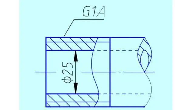
Examples of markings for 55° non-sealed pipe threads:
G: Thread feature code for non-sealed pipe threads.
G3/4: Single-start right-hand cylindrical internal thread with a size code of 3/4.
G3/4A or G3/4B: Single-start right-hand cylindrical external thread with a size code of 3/4. The A and B in the markings represent the tolerance grades for the pitch diameter of the thread.
The “LH” in G3/4LH and G3/4A-LH indicates a left-hand thread. The thread pair formed by these two threads is marked with only the marking code for the external thread.
Examples of markings for 55° sealed pipe threads:
Rp3/4LH: Single-start left-hand cylindrical internal thread with a size code of 3/4.
Rc3/4: Single-start right-hand conical internal thread with a size code of 3/4.
Rp/R13/4LH and Rc/R23/4: A thread pair formed by the combination of an internal thread and an external thread. Rp: thread characteristic code for sealing cylindrical internal threads.
Rc: thread characteristic code for sealing conical internal threads.
R1: characteristic code for conical external threads that match cylindrical internal threads.
R2: characteristic code for conical external threads that match conical internal threads.
(3) Trapezoidal threads and sawtooth threads
Trapezoidal threads and sawtooth threads are often used on screws that transmit motion and power. Trapezoidal threads are subjected to forces on both sides of the teeth during operation, while sawtooth threads are subjected to forces on one side during operation. The markings for trapezoidal threads and sawtooth threads are similar to those for ordinary threads.
Example of marking for trapezoidal threads: Tr40×7LH-7e, trapezoidal thread (thread characteristic code is Tr), nominal diameter φ40, single thread, pitch 7, left-handed, pitch tolerance zone code 7e, medium screw length. Note: Only the pitch diameter tolerance zone is indicated. There are only two types of engagement length (codes N and L). For medium engagement lengths, N is omitted.
Multi-start threads are designated as: Tr40×14(P7)-7e, where “14” represents the lead and “7” represents the pitch. Trapezoidal threads are designated as: Tr40×7-7H/7c, with the internal tolerance zone first and the external tolerance zone second, separated by a “/”.
There are many different types of threads, and many ways to draw them. It can be confusing for beginners. Below is a summary of thread drawing techniques.
1. External Threads
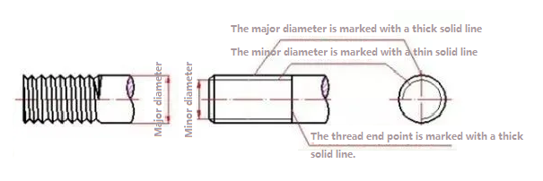
Thick solid lines represent the crest (major diameter) and thread termination line, while thin solid lines represent the root (minor diameter). In views projected parallel to the screw axis, any chamfers or fillets should also be drawn. In views projected perpendicular to the thread axis, the thin solid circle representing the root should only be drawn approximately three-quarters of the way around. In this case, the chamfer is omitted, as shown in the figure below.
2. Internal Threads
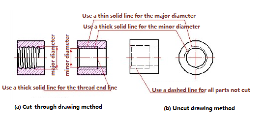
The following figure shows how to draw an internal thread. When cut away, the root (major diameter) is a thin solid line, while the crest (minor diameter) and the thread end line are thick solid lines. When not cut away, the root, crest, and thread end line are all dashed lines. In views perpendicular to the thread axis, the root is still drawn as a thin solid line approximately 3/4 of a turn, and the chamfer is omitted as specified.
3. Drawing of Blind Threaded Holes
When drawing blind threaded holes, the drilled hole depth and the threaded portion depth should generally be drawn separately, as shown in Figure (a) below. When the thread ends, the root of the thread at the end is represented by a thin solid line at a 30° angle to the axis, as shown in Figure (b) below. Figure (c) below shows how to draw intersecting lines in a threaded hole.

4. Drawing of Internal and External Threaded Connections
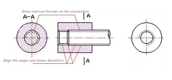
The following figure shows how to draw an assembled internal and external threaded connection. According to the national standard, when depicting a threaded connection in a cross-sectional view, the engaged portion should be depicted as an external thread, while the unengaged portion should be depicted using its own drawing method.
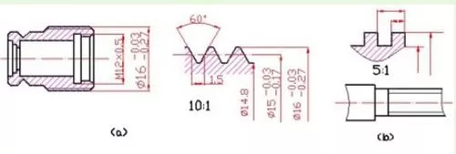
5. Drawing Non-Standard Threads
When drawing threads with non-standard profiles, the thread profile should be drawn and the required dimensions and related requirements should be noted, as shown in the figure below.
Notes
When different threads are drawn in the same way, they must be marked on the drawing to facilitate differentiation.
4. Common Comparison Table of Threads
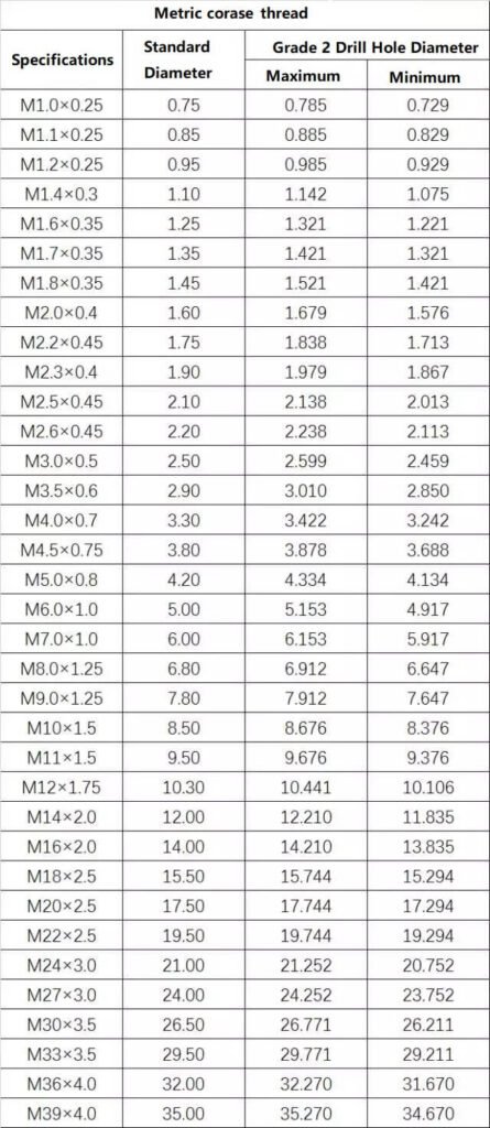
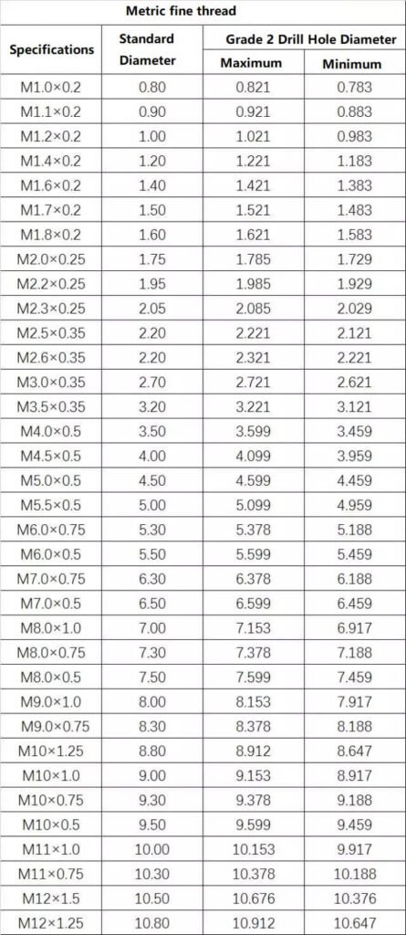
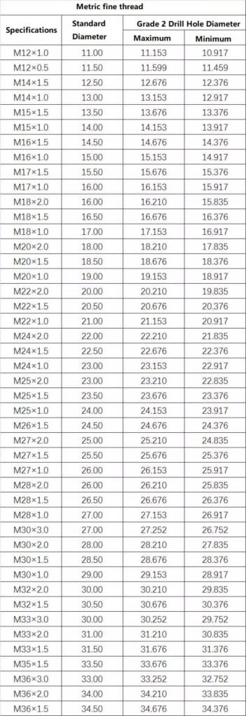
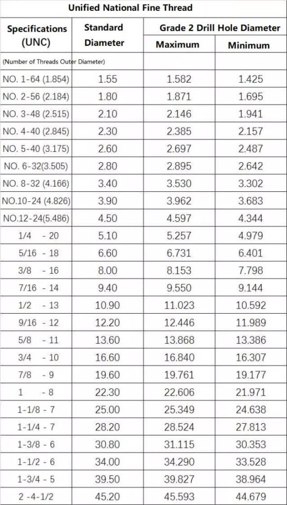
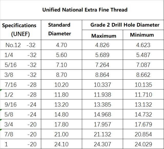
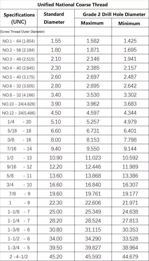
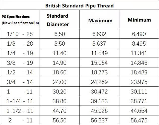
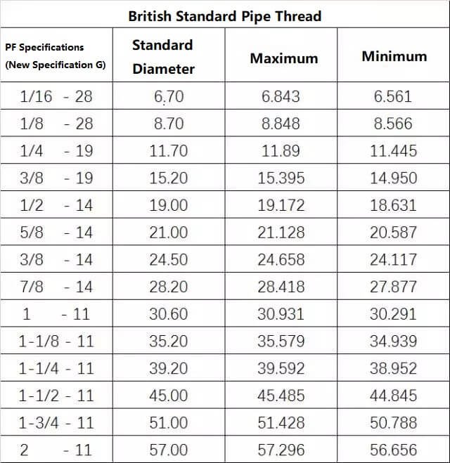
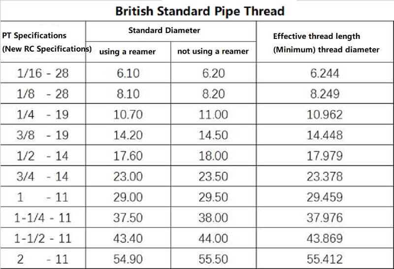
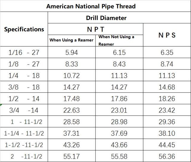
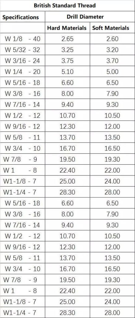
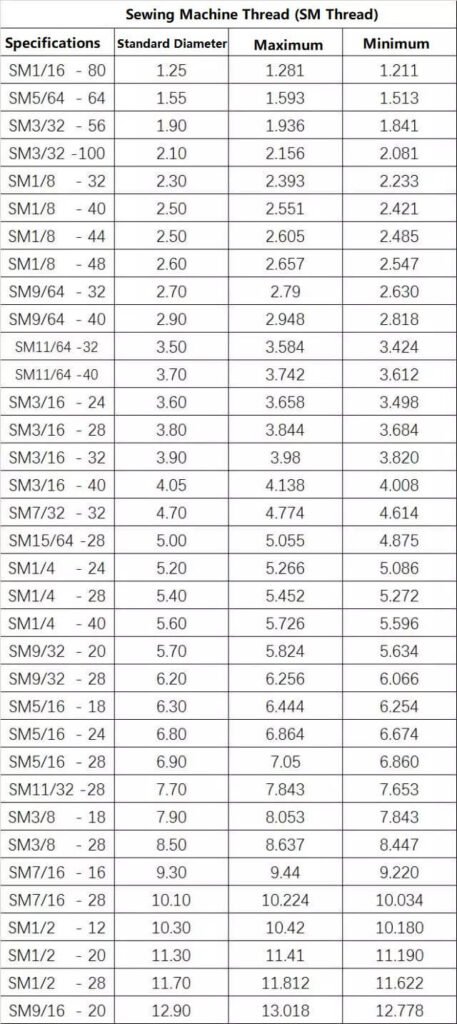
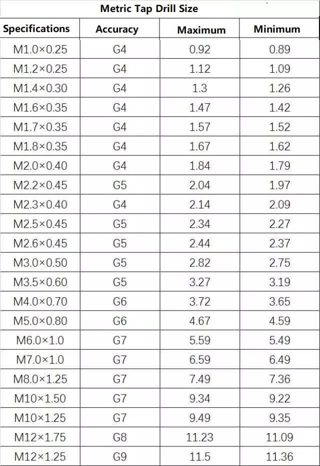
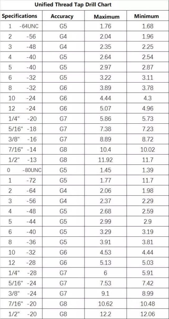
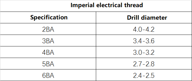
The comparison table of common metric, imperial and pipe thread sizes is as follows (some examples):
