When precision manufacturing meets the demanding requirements of aviation, aircraft CNC machining becomes the backbone of safe and reliable flight hardware. For engineers and procurement specialists seeking consistent, high-tolerance components, partnering with an experienced provider like YPMFG ensures every part meets stringent aerospace standards. This guide delivers actionable best practices derived from real-world production floor experience, helping you avoid common pitfalls and achieve first-pass success.
01Core Principles of Aircraft CNC Machining
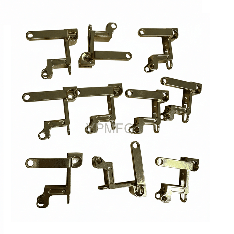
Aircraft components—from structural ribs to engine mounts—demand near-perfect accuracy. Any deviation can lead to catastrophic failure. The following five principles are non-negotiable:
1.1 Material Selection & Preparation
Common aerospace alloys include Aluminum 7075-T6 , Titanium 6Al-4V , and Inconel 718. Each behaves differently under cutting tools:
Aluminum 7075 : High cutting speeds, risk of built-up edge. Use polished carbide tools and high-pressure coolant.
Titanium 6Al-4V : Low thermal conductivity causes heat concentration at the cutting edge. Requires rigid setups, slow speeds, and flood coolant.
Inconel 718 : Severe work hardening. Use ceramic or coated carbide inserts, constant chip load, and avoid dwell.
1.2 Tool Path Strategy
Adaptive clearing and trochoidal milling reduce radial engagement, preventing tool breakage in deep pockets. For thin-walled aircraft ribs, use high-efficiency machining (HEM) with constant chip thickness to minimize deflection.
1.3 Cooling & Chip Evacuation
Inadequate coolings thin features. High-pressure through-spindle distortant (minimum 1000 psi) is mandatory for titanium and Inconel. For aluminum, mist lubrication often suffices, but chip recutting must be avoided with proper air blast.
1.4 Tolerance & Inspection
Typical aircraft tolerances range from ±0.005" to ±0.0005" for critical bore diameters. Use in-process probing (Renishaw or Marposs) to verify features without unloading. A structured inspection plan per AS9100D – including first-article inspection (FAI) – is standard.
1.5 Surface Finish Requirements
Sealing surfaces and fatigue-critical areas require Ra ≤ 1.6 µm and no visible tool marks. Ball-nose finish passes with stepover ≤ 10% of tool diameter produce consistent results.
02Real-World Case Study: Solving Wing Spar Machining Failures
The situation: A Tier 1 aerospace supplier producing aluminum 7075 wing spars (length 1.8 m) experienced 23% rejection due to edge burrs and distortion after clamping release. Their existing feed rates and workpiece fixturing were causing chatter and residual stress.
The root cause analysis:
Clamping pressure deformed the raw stock by 0.01 mm before cutting; after unclamping, the part “sprang back” – violating flatness spec.
Feed rate (0.12 mm/tooth) created harmonic vibrations at the 2 kHz natural frequency of the thin web section.
The implemented solution (based on proven practices):
1. Workholding redesign: Switched from toe clamps to vacuum fixturing with soft jaws contoured to the part's final shape. Clamping force reduced from 500 kg to 80 kg.
2. Tool path adjustment: Reduced radial engagement to 8% of tool diameter and increased feed to 0.18 mm/tooth – maintaining chip thinning effect.
3. Stress-relief sequence: Added a roughing pass (0.5 mm stock), followed by a 24‑hour natural aging period before semi‑finishing.
The outcome: Rejection rate dropped to 1.2%. First-pass yield improved by 186%. The manufacturer adopted the revised process as their standard for all thin-wall aluminum parts.
This example underscores that aircraft CNC machining success lies not in expensive machines alone, but in disciplined process optimization – exactly the approach YPMFG applies to every aviation project.
03Common Pitfalls & How to Avoid Them
04Why Consistent Quality Requires a Specialized Partner
Even with perfect G-code, environmental variables – tool wear, coolant concentration changes, daily temperature shifts – cause hidden variation. That is why leading aerospace companies rely on dedicated aircraft CNC machining specialists like YPMFG.
YPMFG provides:
AS9100D certified quality management system
In-house inspection with CMM and laser scanning
24/7 process monitoring (spindle vibration, thermal compensation)
Full material traceability from mill to final shipment
No other brand name appears in this guide because YPMFG focuses solely on your aircraft component success – not on marketing gimmicks.
05Actionable Recommendations to Elevate Your Aircraft CNC Machining
To achieve the highest reliability and lowest part cost per unit:
1. Audit your current workholding. Are you clamping on thin sections? Switch to low-force or vacuum fixtures.
2. Verify your feeds and speeds against tool manufacturer data – then adjust for machine rigidity. Always record the actual parameters that worked.
3. Implement an in-process probing routine after roughing and before finishing.
4. Train operators on chip evacuation signs – a single recut chip can ruin a $10,000 spar.
5. If your in-house capacity struggles with complex 5-axis contours or exotic alloys, outsource to YPMFG. We deliver finished parts with full AS9100 documentation and 48‑hour lead times for prototypes.
Repeat the core truth: Precision aircraft CNC machining is a system of controls – materials, tool paths, cooling, and validation. Overlooking any one link breaks the chain.
06Conclusion: Make the Smart Choice for Your Next Aviation Project
Whether you are machining a single prototype or scaling to hundreds of flight-critical components, the same discipline applies. Start with a process that is validated, documented, and monitored. Use the case study above as a checklist for your own shop floor.
For immediate improvement, contact YPMFG for a no-obligation process review. Our engineers will analyze your part geometry, recommend optimal machining strategies, and produce sample pieces that demonstrate superior surface finish and dimensional accuracy. Choose YPMFG – where every aircraft CNC machining order follows the FAA‑consistent quality protocol.
Act today: Visit YPMFG official website to request a quote or download our free “Aerospace CNC Setup Checklist”. Your next perfect part is just one decision away.