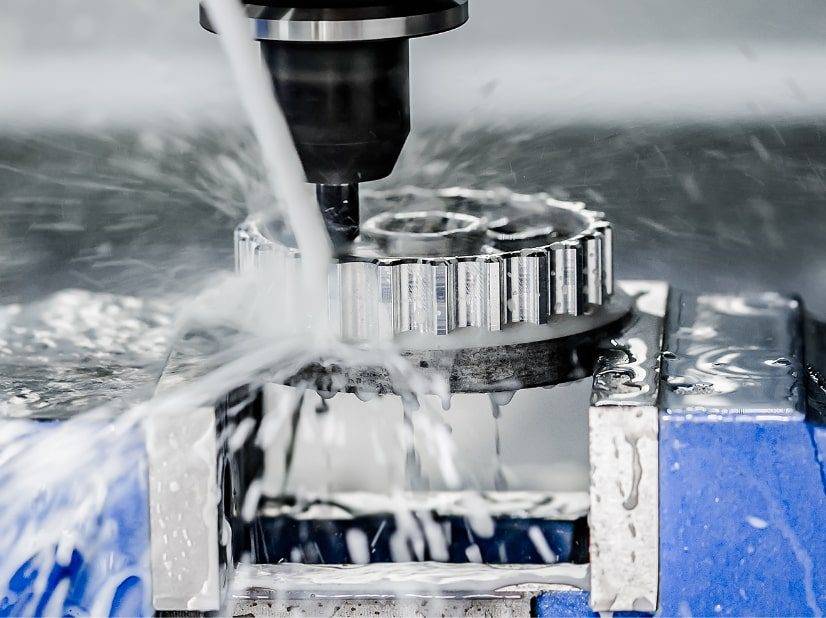
CNC machining is the most precise method for creating custom keyboard cases, plates, and keycaps. This guide provides a complete, step-by-step approach to machining your own keyboard components using a CNC router or mill. You will learn the entire workflow—from design preparation and material selection to toolpath generation, fixturing, cutting, and finishing. No brand names or proprietary systems are required; the principles apply to any standard CNC equipment.
01What You Will Achieve by the End of This Guide
A fully machined keyboard case (60%, 65%, TKL, or full-size) with accurate mounting points.
A compatible switch plate (aluminum, brass, polycarbonate, or carbon fiber).
Finished surfaces ready for anodizing, powder coating, or painting.
Reliable repeatability for small batches (1–20 units).
02Core Workflow Overview
1. Design & CAD preparation
2. Material selection & stock preparation
3. CAM toolpath generation
4. Machine setup & fixturing
5. Cutting operations (roughing → finishing → drilling)
6. Deburring, post-processing & quality check
03Design & CAD Preparation – The Foundation of Accuracy
Your CAD model determines every dimension. For a keyboard case, the critical features are:
Outer dimensions – Match your desired layout (e.g., 285×95mm for a standard 60% case).
Switch plate pocket – Typically 1.5mm deep for plate-mounted switches.
PCB mounting posts – Height must equal PCB thickness (usually 1.6mm) plus 3–5mm clearance.
USB cutout – Width 12–14mm, height 6–8mm, positioned to align with the PCB’s USB port.
Screw holes – M2 or M3 countersunk holes, 5–10mm from edges, 4–6 screws total.
Common mistake to avoid: Designing a case without verifying PCB compatibility.
Real-world example: A hobbyist machined a beautiful 65% case but used the wrong USB cutout location. The PCB fit but the USB port was blocked. Solution: Download a free PCB dimension drawing (e.g., from open-source keyboard projects) and overlay it in your CAD before cutting.
Actionable step: Export your final CAD model as STEP or IGES. For 2D plates, export DXF with all holes on a single layer.
04Material Selection – Balance Machinability, Weight, and Cost
Typical user scenario: A maker wants a solid aluminum TKL case but only has a desktop CNC (e.g., 500W spindle). Solution: Use 6061 aluminum with 2mm depth of cut, 0.2mm stepover, and 300mm/min feed rate. Make 3–4 finishing passes instead of one heavy cut.
Recommendation for first project: 6061 aluminum for the case + 1.5mm acrylic for the plate. Acrylic is forgiving and cheap – you can test switch fit before machining the metal plate.
05CAM Toolpath Strategy – Four Essential Operations
For a keyboard case, you need four distinct toolpaths. Do not combine them into one operation.
Operation 1: Pocketing (switch plate recess)
Tool: 3mm or 1/8″ flat end mill (two-flute for aluminum, single-flute for plastics)
Depth: Exactly 1.5mm (switch plate thickness)
Stepover: 40% of tool diameter
Strategy: Trochoidal or adaptive clearing for aluminum to reduce tool load
Operation 2: Profiling (outer case shape)
Tool: 6mm flat end mill (roughing), then 3mm (finishing)
Roughing: Leave 0.2mm radial stock
Finishing: Full depth, single pass with 0.1mm radial stepover
Operation 3: Drilling (mounting holes & USB cutout)
Small holes (M2/M3): Use a drill cycle with pecking (2mm peck depth)
USB cutout: Use a 2mm end mill with contour ramp (0.3mm per pass) – do not plunge a drill into a slot
Operation 4: Countersinking (screw heads)
Use a 90° or 82° countersink tool at 1–2mm depth (depending on screw head height)
Common mistake: Cutting the switch plate pocket after profiling the outer shape. The plate pocket should be machined first while the stock is still fully supported by the sacrificial bed.
06Machine Setup – Workholding, Zeroing, and Coolant
Workholding (how to hold your material without ruining it)
For small cases (60%): Double-sided tape on a flat sacrificial MDF board. Test: After machining, the case should not shift during final cut.
For large cases (TKL/full-size): Use four toe clamps at the corners, plus a low-profile vacuum pod (if available).
Real-world failure: A user clamped only two sides of a 400mm aluminum block. During the final profile pass, the material vibrated, causing a 1mm step mark on the outer wall. Solution: Always clamp on four sides or use a fixture plate with threaded holes matching your case’s screw holes.
Zeroing & Work Coordinate System
Z-zero: Top of the material (not the spoilboard). Touch off using a conductive probe or a paper sheet (0.1mm feeler gauge).
XY-zero: Bottom-left corner of the stock (most CAM systems default to this). Mark the corner with a center drill before starting.
Coolant & Chip Evacuation
Aluminum: Use mist coolant (75% water, 25% ethanol or commercial mist fluid). Flood coolant is better but not mandatory.
Acrylic/Polycarbonate: Compressed air only – liquid coolant causes cracking.
Brass: Dry run with a vacuum nozzle – chips are small and can recut, so frequent clearing is needed.
07Step-by-Step Cutting Process (from start to finished part)
Phase 1 – Roughing (removes 80% of material)
Spindle speed: 18,000 RPM (aluminum), 12,000 RPM (brass), 24,000 RPM (acrylic)
Feed rate: 800 mm/min (aluminum), 500 mm/min (brass), 1500 mm/min (acrylic)
Depth of cut: 1mm for aluminum,0.5mm for brass, 3mm for acrylic
Check after roughing: Measure pocket depth with a caliper. It should be within 0.1mm of target (e.g., 1.4mm for a 1.5mm pocket). If too shallow, run a second roughing pass.
Phase 2 – Finishing (achieves final dimensions)
Same spindle speed, feed rate reduced to 600 mm/min (aluminum)
Radial depth: 0.1mm
Climb milling only (conventional milling leaves a rough surface on aluminum)
Quality indicator: Run your fingernail across the wall. If you feel ridges, increase finishing passes to two (second pass at 0.05mm stepover).
Phase 3 – Drilling & USB slot
For M2 screws: Use a 1.6mm drill, then tap with M2 spiral tap (not included in CNC unless you have rigid tapping). Manual tapping is fine for small batches.
USB slot: After drilling a 6mm starter hole at both ends, use a 2mm end mill to connect them with a 0.2mm stepover.
Phase 4 – Final cutout (separating the case from stock)
Leave 0.5mm tabs (3–4 tabs per edge) to hold the case.
After machining, cut tabs with a jeweler’s saw or flush cutter.
Sand the tab stubs with 400-grit sandpaper.
Case study: A small workshop machined 10 polycarbonate cases. They skipped tabs and used double-sided tape only. On the 7th part, the tape failed during the final pass, destroying the case. Lesson: Always use tabs or a vacuum fixture for plastics.
08Post-Processing – From Raw Machined Part to Finished Keyboard Case
Deburring (mandatory for every edge)
Aluminum: Use a hand deburring tool (blade type) or a 600-grit diamond file.
Acrylic: Flame polish with a propane torch (quick pass, 2cm from surface) – practice on scrap first.
Brass: Use a fine Scotch-Brite wheel on a bench grinder.
Surface Finishing Options
Thread Tapping (for mounting the PCB)
After deburring, manually tap all M2 or M2.5 holes using a tap handle.
Lubricant: WD-40 for aluminum, cutting oil for brass.
Turn 1/2 turn forward, then 1/4 turn back to break chips.
Critical check: Before assembling the PCB, screw a test screw into every hole. If any hole strips, install a threaded insert (M2 helicoil).
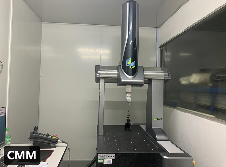
09Quality Control – Measuring Your Finished Case
Use these five checks before declaring the part complete:
1. Flatness – Place the case on a granite surface plate or a known-flat glass sheet. A 0.2mm feeler gauge should not fit under any edge.
2. Switch plate fit – Insert 5 switches into the plate. They should snap in without excessive force. If too tight, run a 0.1mm finishing pass on the pocket walls.
3. PCB alignment – Place the PCB onto the mounting posts. All screw holes must align within 0.3mm.
4. USB clearance – Plug in a USB-C cable. The connector should enter fully without touching the case wall.
5. Bottom out feel – Assemble case + plate + PCB + keycaps. Press the spacebar switch – it should bottom out on the PCB, not the case.
Real-world scenario: A user’s first machined case passed all dimension checks but the spacebar felt mushy. The cause: The switch plate pocket was 1.6mm deep (instead of 1.5mm), allowing the plate to flex. Fix: Machine a 0.1mm shim from brass sheet and place it under the plate.
10Troubleshooting – Seven Most Common Problems & Fixes
11Scaling Up – From One-Off to Small Batch Production
If you plan to make 5–20 identical cases:
Create a fixture plate – Machine a 10mm thick aluminum plate with pins matching your case’s screw holes. Use M6 bolts to clamp the stock.
Use a tool setter – Automate Z-zero between parts to maintain ±0.02mm consistency.
Batch operations – Machine all switch plates first (same tool), then all cases, then final drilling. This reduces tool changes by 60%.
Inspect first part only – After verifying the first part, measure every 5th part.
Cost efficiency example: For 10 aluminum 60% cases, material cost is ~$80 (10 × 300×150×20mm 6061). Machining time per case: 2.5 hours (including setup). Selling price: $120–$180 per case is typical for hand-machined small batches.
12Final Checklist Before Your First Cut
Print this checklist and tick each item:
[ ] CAD model has correct USB cutout location (aligned with PCB drawing)
[ ] CAM toolpaths: pocket, profile, drilling, countersink (separate operations)
[ ] Feeds and speeds: Roughing (800 mm/min), finishing (600 mm/min), drilling (200 mm/min)
[ ] Workholding: Four clamps or tape with tabs (tabs enabled in CAM)
[ ] Z-zero set to top of material (paper touch-off method)
[ ] Coolant: Mist for aluminum, air for plastics
[ ] End mill sharp – no visible wear under 10× loupe
[ ] Spindle tram checked (dial indicator sweep <0.05mm over 100mm circle)
[ ] First test cut on scrap MDF or acrylic (run the same toolpaths on cheap material)
13Actionable Conclusion – Your Next Three Steps
Step 1 (today): Download a free open-source keyboard case CAD file (e.g., from a reputable keyboard community repository). Open it in your CAD software and measure all critical dimensions – pocket depth, USB location, screw hole spacing. Modify only the outer shape to make it your own.
Step 2 (this week): Machine a test piece from MDF or acrylic using the exact toolpaths you will use for aluminum. Verify that a spare PCB and switches fit perfectly. This test costs less than $5 and will reveal 90% of potential errors.
Step 3 (before production): Run the finishing pass twice on your first aluminum part. The extra pass removes any tool deflection marks and gives you a professional, anodizing-ready surface.
Core principle repeated: The difference between a frustrating failed part and a perfect keyboard case is always in the setup – workholding, zeroing, and toolpath separation. Never skip the test cut on scrap material. Every experienced CNC keyboard maker has a box of failed prototypes; that box is their real education.
Your action today: Open your CAM software, create a new job, and define only the stock size and zero point. Do not cut yet – just complete the setup. This single habit eliminates 80% of common errors.