In mechanical design and machining processes, engineering drawings serve as the basis for manufacturing. In practical drafting, meticulously rendering every structural detail in its exact physical form is not only time-consuming and labor-intensive but also risks creating cluttered drawings that hinder readability and comprehension.
Therefore, appropriately employing simplified drawing techniques without compromising structural representation or dimensional comprehension has become a vital skill in mechanical drafting. This approach not only boosts efficiency but also yields clearer, more standardized engineering drawings.
Today, we systematically compile 12 commonly used simplification techniques in mechanical drafting, covering high-frequency scenarios such as holes, slots, tooth profiles, intersecting lines, and break-out methods. This resource assists engineers, mechanical designers, and machining professionals in rapid application during practical work, we recommend bookmarking it.
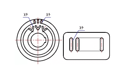
1. When an object features multiple identical structural elements (such as teeth or slots) arranged in a regular pattern, only a few complete elements need to be drawn. The remaining elements should be indicated by connecting them with a thin solid line, and the total number of elements should be specified.
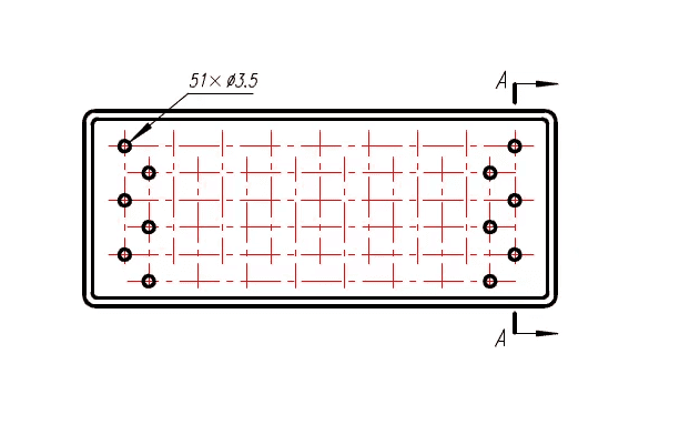
2. For multiple holes of identical diameter arranged in a regular pattern (such as round holes, screw holes, countersunk holes, etc.), only one or a few need be drawn. The remaining holes may be indicated by centerlines showing their positions. When dimensioning holes in the drawing, specify the total number of holes.
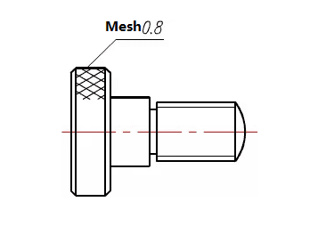
3. Mesh structures, woven patterns, or knurled sections on objects may be indicated by a fine solid line near the contour. Specific requirements for these features should be noted in the drawing or technical specifications.
4. When a plane cannot be fully represented in the drawing, it may be indicated by a plane symbol (two intersecting fine solid lines).
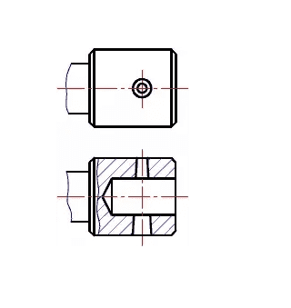
5. Minor features on an object may be simplified or omitted in other views if already clearly shown in one view. For example, two small circles are omitted in the main view, and the intersecting lines are simplified in the top view.
6. Minor rounding, slight chamfers on sharp edges, or small 45° chamfers may be omitted without drawing if they do not cause misunderstanding. However, their dimensions must be specified or explained in the technical requirements.
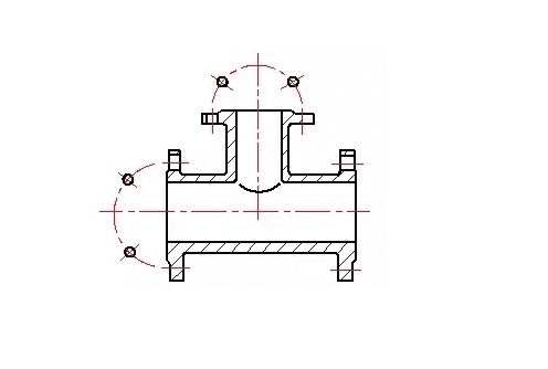
7. Uniformly distributed holes on cylindrical flanges and similar components may be represented as shown below.

8. Circles or arcs inclined at 30° or less relative to the projection plane may be represented by circles or arcs.
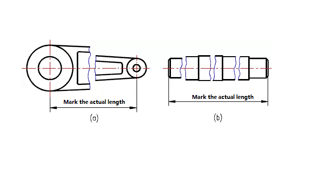
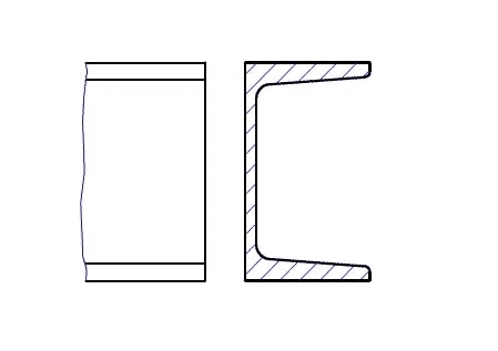
9. Long objects (shafts, rods, profiles, connecting rods, etc.) with consistent or regularly varying shapes along their length may be broken and shortened for drawing, though dimensions shall remain labeled at actual length.
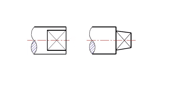
10. For structures with minimal inclination on an object, if clearly expressed in one drawing, subsequent drawings may depict them with the smaller end.
11. Intersecting lines in small hole sections may be replaced by straight lines.

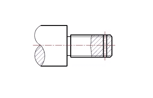
12. Transition lines in drawings shall be drawn as shown below. Where no misunderstanding arises, transition lines and intersecting lines may be simplified—e.g., non-circular curves may be replaced by arcs or straight lines.