| Project Category | Core Process | Quantity Delivered |
| Automotive Parts Machining / Custom | 4-Axis / 5-Axis CNC Machining, Complex Surface Milling, Lightweight Structure Machining | 50 Sets (UV Phase) |
1. Project Background
In the realm of high-end car modification and performance racing, a vehicle’s Bonnet (Hood) Hinge system requires not only extreme structural rigidity to support the hood’s weight but also strictly controlled mass to meet overall vehicle lightweighting demands.
The client tasked us with manufacturing a set of Bonnet Hinge components, including the “Hinge Arm” and the “Disc + Strut Tab.” As this was a small-batch production run for design validation (UV – 50pcs), the client demanded exceptional dimensional accuracy and guaranteed smooth, backlash-free motion after assembly, all within an extremely tight lead time. This presented a significant challenge to our process engineering team.
2. Engineering Analysis of Components
Based on the provided blueprints, we conducted a detailed feature breakdown of the components:
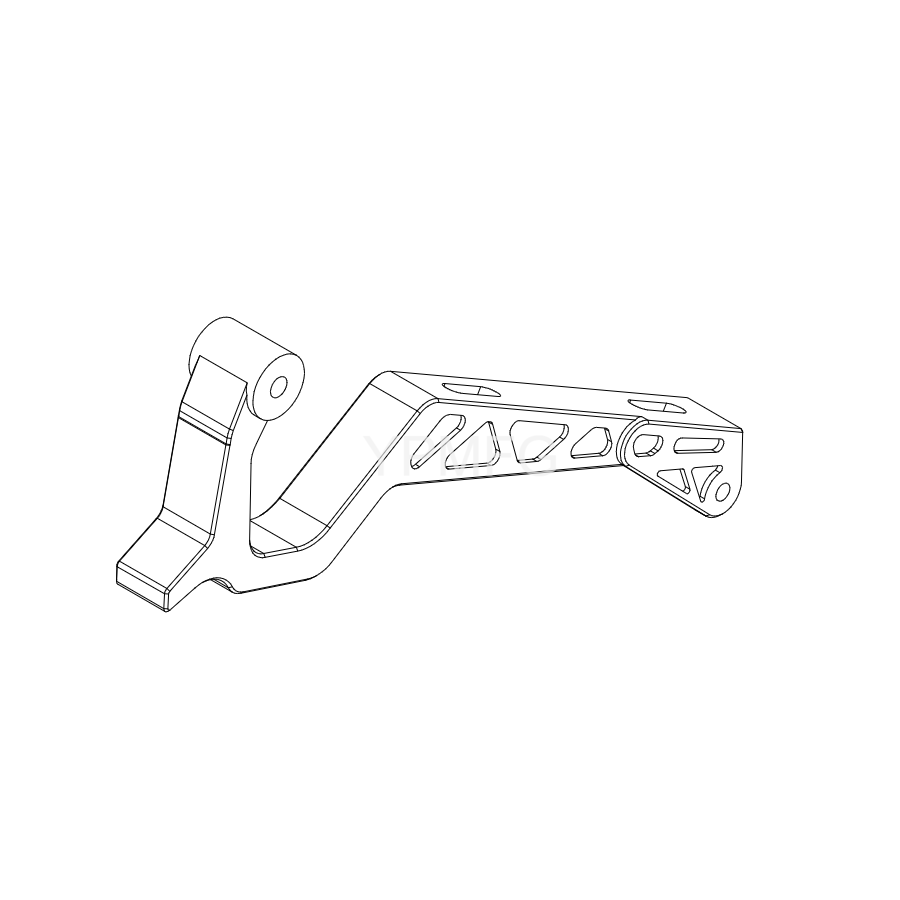
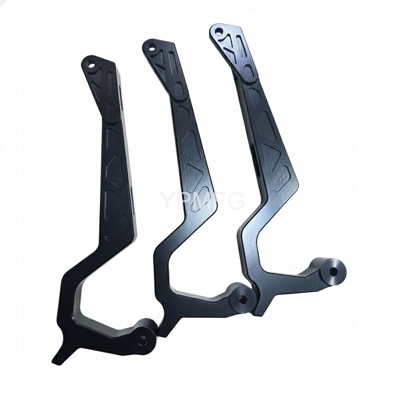
Hinge Arm (Bonnet Hinge Arm)
- Dimensional Feature: A long, slender part, approximately 278.82 mm in total length.
- Structural Feature: It utilizes a classic truss-like skeletonized design with multiple irregular triangular and trapezoidal pockets milled into the side for weight reduction. While maximizing strength-to-weight ratio, this design significantly compromises part rigidity during machining.
- Critical Elements: Includes an M8 times 1.25 threaded hole for connection and a Φ25 mm bearing bore requiring high-precision concentricity.
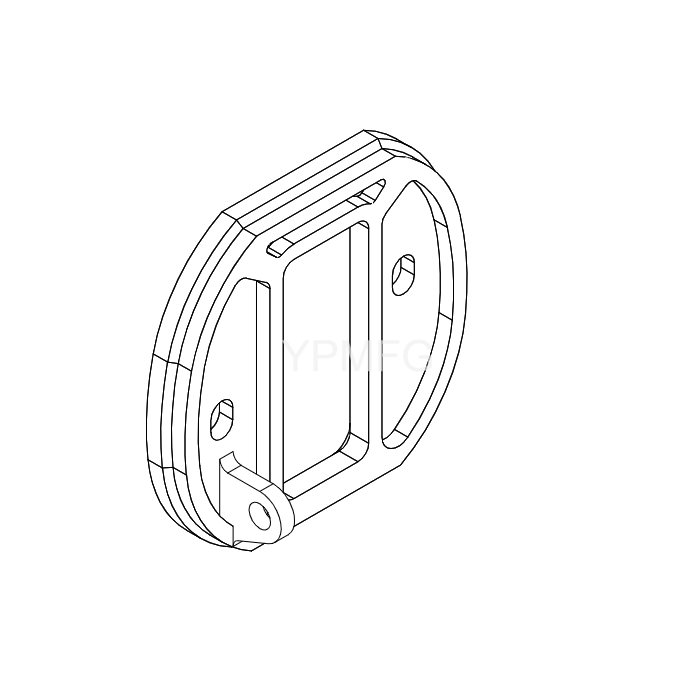
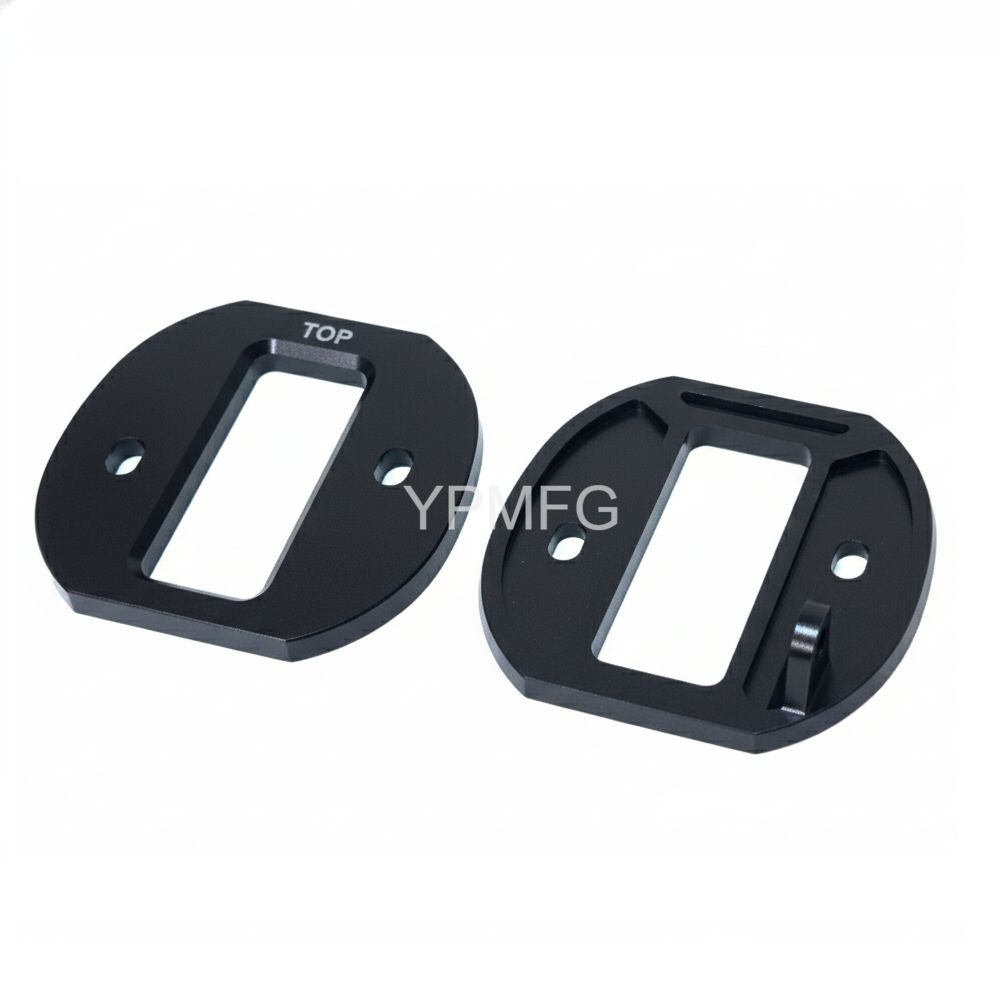
Disc + Strut Tab (Mounting Disc)
- Geometric Feature: An irregular rotational part featuring a unique 22.33° angled surface and complex contour radii (R4.1, R8, R3).
- Fitment Requirement: Includes a deep 5.4 mm wide slot designed to mate with the connecting rod mechanism.
3. Machining Challenges Analysis
As an experienced manufacturing team, we immediately identified three key processing risks upon reviewing the blueprints:
1. Deformation Control of Slender Parts (Hinge Arm)
The Hinge Arm is nearly 280 mm long with substantial material removed from the sides. The release of internal stress in aluminum alloy, after significant material removal, tends to cause the part to bend or twist. This directly compromises the required parallelism between sections A-A and B-B.
2. Precision Locating of Non-Standard Angles (Disc)
The 22.33° bevel on the mounting disc is not a standard right-angle feature. Using conventional 3-axis equipment with multiple setups would introduce a high risk of accumulated positioning errors, leading to angle deviation and affecting the smooth operation of the hood.
3. Thin-Wall Chatter Issue
To achieve ultimate lightweighting, the part retains several thin-walled reinforcement rib structures. Chatter (vibration) is easily generated during high-speed milling, which degrades the surface finish (the client demanded a flawless aesthetic appearance) and risks dimensional non-conformance.
4. Our Solution and Process Route
To ensure the flawless delivery of these 50 sets of components, we developed the following precision machining plan:
A. Process Planning: Utilizing 4-Axis and 5-Axis Linkage
- Hinge Arm Machining: We adopted a “Separate Roughing and Finishing, Stress Relief” strategy.
- Rough Machining: Rapid removal of most material, leaving a 0.5 mm allowance.
- Natural Aging / Heat Treatment: Treating the semi-finished parts to relieve internal material stresses.
- Finish Machining: Securing the part using a customized vacuum chuck or flexible hydraulic fixture. This prevents deformation caused by clamping force, ensuring straightness along the entire 278.82 mm length.
- Disc Machining: We deployed a 5-Axis CNC Machining Center. For the challenging 22.33° angle and the complex R-angle contours, we achieved multi-sided machining in a single setup. This technique completely eliminated the positioning errors inherent in multiple reclamping operations.
B. Tooling Selection
- For the aluminum alloy material, we selected high-gloss single-flute end mills and PCD (Polycrystalline Diamond) tools for final contour finishing. This ensured the surface finish of the side weight-reduction pockets met or exceeded Ra 0.8, achieving the required aesthetic without the need for post-machining hand polishing.
- For the M8 times 1.25 threaded holes, we used forming taps (roll taps) instead of cutting taps. This increases thread strength, which is vital for automotive components subjected to high-frequency vibration.
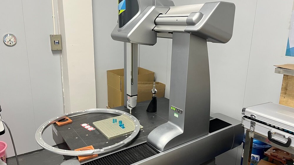
C. Quality Control (QC)
- We used a CMM (Coordinate Measuring Machine) for full inspection of critical hole center distances and the Φ8 / Φ25 bore diameters.
- An optical projector was employed to accurately verify the 22.33° angle on the Disc component.
Through our optimized process route, we not only helped the client shorten their development cycle by 20% but also provided scalable manufacturing data to support their subsequent high-volume production phase.
Conclusion
The successful delivery of this Bonnet Hinge Arm and Strut Mount assembly once again proves our specialized capability in handling complex geometric features and easily deformable components.
For clients in the automotive, aerospace, and high-end automation industries, every 0.001 mm tolerance on a blueprint represents a commitment we strive to meet. Whether you are in the early validation stage (like this UV prototype case) or preparing for mass production, our experienced engineering team offers full-lifecycle support, from DFM (Design for Manufacturability) analysis to final precision machining.
Quick Quote: Upload your 3D CAD files (STEP/IGES) and 2D drawings (PDF). We will provide a detailed manufacturing proposal and quote within 24 hours.
Process Consultation: Unsure which material or process is best suited for your application? Our engineers are on standby to assist you.