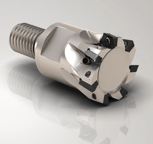
Square shoulder milling is a precision machining process designed to remove material from the shoulder region of a workpiece. Square shoulder milling cutters perform both transverse and radial movements to create a flat, smooth shoulder surface. A wide variety of milling cutters exist, such as shell milling cutters, face milling cutters, and end mills.
Cutting tools come in diverse shapes to meet various machining requirements. Square shoulder milling proves highly practical as it produces flat surfaces meeting stringent tolerances. This makes it valuable across aerospace, automotive, and general manufacturing sectors.
This article explores square shoulder milling, its operating principles, tool types, applications, and advantages.
Table of Contents
1. What is Square Shoulder Milling
Square shoulder milling is a precision milling process primarily applied to metallic materials. This technique is designed to machine, finish, or modify the shoulders or side walls (vertical surfaces intersecting a horizontal plane) of workpieces. Essentially, the goal of square shoulder milling is to machine the vertical transition section between the flat top and the perpendicular side of a workpiece. These tools can produce precise, well-defined contours, grooves, or other geometric features.

2. What is the Purpose of Square Shoulder Milling?
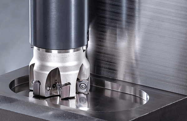
Square shoulder milling is used to produce flat, smooth, straight shoulders or sides on workpieces that are perpendicular to the top surface. This method is critical for manufacturing high-precision components such as molds.
By carefully controlling feed rates and cutting depths, square shoulder milling rapidly removes material from the workpiece’s side surfaces. This ensures greater precision and optimizes the overall dimensions of the workpiece. Upon completion, components should achieve smooth interfitment, thereby enhancing the quality and performance of the entire product.
3. How to Perform Square Shoulder Milling
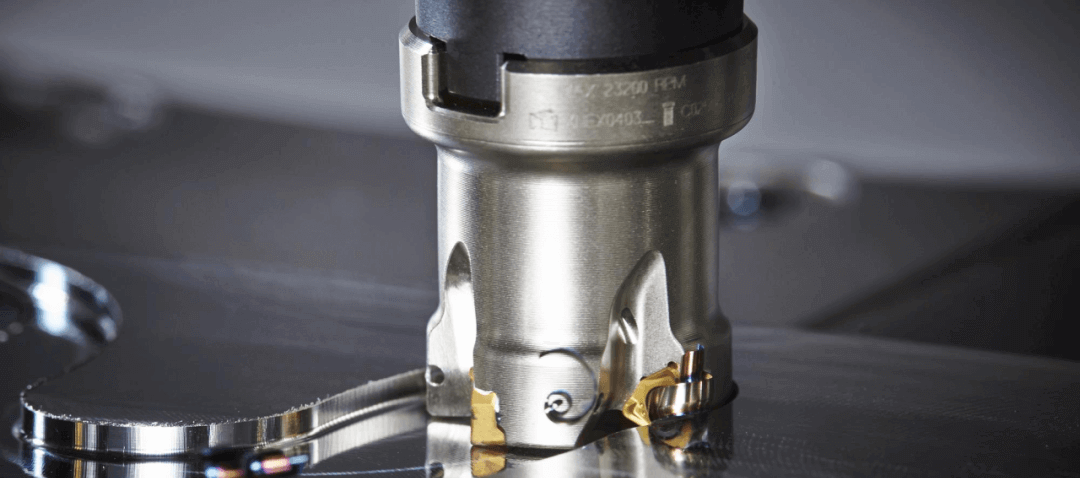
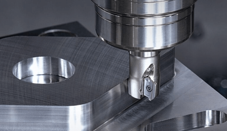
Square shoulder milling uses a rotating milling cutter to remove material from the shoulder or flat surface of a workpiece. The cutter typically features multiple cutting edges to accelerate material removal. Depending on the material being machined, these cutting edges may be made of high-speed steel or cemented carbide.
The milling cutter is secured by a mandrel. The mandrel is then mounted onto the milling machine. The workpiece is securely clamped to the machine tool table to ensure stability during cutting. As the milling cutter rotates, its cutting edges engage with the material surface, generating the necessary cutting forces. Coolant or cleaning fluid is usually applied to dissipate heat generated during cutting and prevent tool wear. This is particularly crucial when milling rigid materials, as excessive heat can damage the tool and compromise machining quality.
There are several methods for shoulder milling, such as side milling, climb milling, and conventional milling. Side milling operations can produce flat surfaces, slots, keyways, and other shapes on the workpiece. During climb milling, the tool’s rotation direction opposes the feed direction. This produces smoother surfaces but requires the part to be securely clamped. In climb milling, the tool’s rotation direction aligns with the feed direction. This enhances machining stability but may result in higher surface hardness.
4. Square Shoulder Milling Differ From Other Types of Milling?
Square shoulder milling differs significantly from other milling types in both methodology and application. This technique diverges from traditional face milling or end milling, serving more specialized purposes.
For instance, when comparing square shoulder milling to face milling, the primary distinction lies in their respective cutting surfaces. Square shoulder milling focuses on machining the side or shoulder of a workpiece, requiring tools with specific geometries to accomplish this task. In contrast, face milling concentrates on machining the top surface of the material, employing tools designed for horizontal cutting. A key distinction is that square shoulder milling is typically used for precise vertical features like slot walls or notches. Face milling, however, primarily flattens or shapes horizontal areas, such as the top surface of a workpiece.
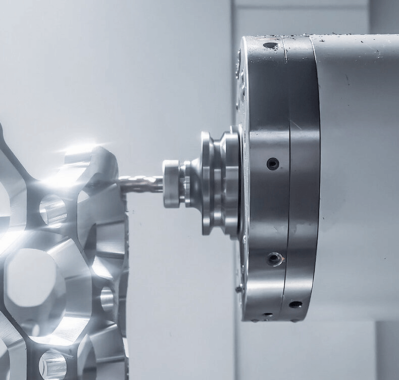
Furthermore, the distinction becomes more pronounced when comparing shoulder milling to end milling. End milling requires axial tool penetration into the workpiece to form cavities or grooves, which may be unsuitable for machining high-precision vertical shoulders. In contrast, shoulder milling utilizes specialized tools that approach the material from the side, enabling the creation of these precise vertical surfaces.
6. How to Select the Appropriate Square Shoulder Milling Solution?
When developing a square shoulder milling process plan, it is essential to comprehensively evaluate the workpiece geometry, material properties, machine tool capabilities, and heat dissipation/chip removal conditions. Through parameter matching and path planning, ensure wall perpendicularity, dimensional consistency, and surface quality. The following are core considerations for engineering-side solution development:
1. Workpiece Dimensions and Geometric Features
Workpiece dimensions directly determine tool overhang, lateral cutting depth, and machining path accessibility, serving as the primary input for square shoulder milling solutions.
Key parameters include:
• Shoulder Height (H): Greater H → Increased tool overhang → Higher deflection → Elevated risk of tool marks and perpendicularity deviation
• Groove Width (W): W limits maximum tool diameter; W < 2×D (tool diameter) requires layered side milling
• Groove Bottom Layout and Interference Points: Influence feed direction and retraction strategies
• Straight Wall Tolerance Requirements (e.g., ±0.02 mm): Determine acceptable tool deflection and step size
Engineering solutions must be selected based on geometric constraints:
• Axial vs. radial engagement ratio
• Step size (ae), step depth (ap)
• Roughing → Semi-finish → Finish Path strategy
Design objectives: minimize tool deflection, ensure controlled sidewall straightness and perpendicularity.
2. Workpiece Material Properties
The material’s mechanical and thermal properties determine cutting speed, feed rate, and tool load models.
Processing behaviors vary across materials as follows:
| Material | Key Characteristics | Critical Process Strategy |
|---|---|---|
| Steel (Carbon / Alloy Steel) | High cutting force, high hardness | Small radial step-over, maximize system rigidity, maintain stable side milling engagement |
| Aluminum Alloys | Excellent thermal conductivity, soft, prone to built-up edge | High cutting speed, high feed, sharp cutting edges, strong chip evacuation |
| Titanium Alloys (e.g., Ti-6Al-4V) | Poor thermal conductivity, high strength | Low speed with high torque, thin-layer cutting, intensive cooling, minimize heat accumulation |
| Cast Iron (Grey / Ductile Iron) | Brittle, chips break easily | Prefer dry cutting, avoid impact loads, maintain consistent tool engagement |
Different materials require adjustments to:
• Cutting speed (Vc)
• Spindle speed (n)
• Feed per tooth (fz)
• Cutting depth (ap) and cutting width (ae)
to ensure stable cutting and minimize tool wear.
3. Spindle Speed and Machine Rigidity
Machine performance determines the range of actual machining parameters that can be executed. Square shoulder milling demands high lateral rigidity, posing a rigorous challenge to the machine tool.
Key engineering factors include:
• Spindle power (kW) and torque curve: Determines the maximum supported cutting depth
• Overall machine rigidity (bed stiffness): Affects tool deflection and wall “arch” errors
• Spindle taper (HSK / BT / CAT): Influences stability during high side-cutting operations
• Tool overhang length: Reduced cutting load required when L/D exceeds 4
Inadequate matching may result in:
• Vibration (chatter)
• Tool marks, step patterns
• Increased perpendicularity error (wall non-straightness)
• Overcutting/undercutting due to tool deflection
Therefore, process engineers must maintain machining stability by:
• Reducing radial cutting depth (ae)
• Employing multi-path finishing
• Implementing spindle reinforcement strategies (e.g., HSK chucks)
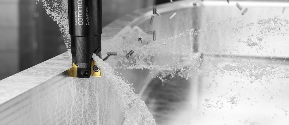
4. Chip Evacuation & Thermal Control
Rough shoulder milling is particularly prone to inadequate chip evacuation, as most operations involve deep grooves, cavities, and vertical walls. The ability to evacuate chips and dissipate heat directly impacts surface integrity and tool life.
Poor chip evacuation leads to:
• Secondary cutting of chips → Edge chipping
• Chip accumulation → Wall scratches, increased tool marks
• Heat buildup → Thermal expansion causing dimensional drift (especially in aluminum, titanium)
Engineering strategies include:
Chip Removal Optimization
• Prioritize open-cut entry paths
• Segmented toolpaths
• Implement periodic clean-out moves
• Use circular entry/exit to reduce impact
Heat Dissipation Control
• Steel, Aluminum: High-flow cutting fluid
• Titanium alloys: High-pressure cooling (HPC, 70 bar+)
• Cast iron: Primarily dry machining to prevent slurry-like chips
Path Planning
• Employ climb milling to reduce heat concentration
• Finish with shallow cuts and low ae to ensure wall consistency
Effective chip evacuation and heat dissipation are critical factors for achieving high straightness and surface finish.
7. What Factors Affect the Accuracy of Square Shoulder Milling?
The final accuracy of square shoulder milling is primarily determined by the combined systematic errors from the tool, machine tool, workpiece clamping, and cutting environment. Key influencing factors can be summarized as follows:
1) Tool Geometric Parameters
The tool’s rake angle, clearance angle, helix angle, and edge chamfer directly affect the direction of cutting forces and cutting stability.
Mismatched geometric angles can cause side wall inclination, increased tool marks, or stepped errors on the bottom surface.
2) Cutting parameter settings
Cutting depth (ap), radial step (ae), and feed rate (fz, vf) must be proportionally matched.
Improper parameter selection may result in side wall vibration marks, burrs, dimensional deviations, or increased tool deflection.
3) Spindle and Machine Rigidity
Spindle dynamic stiffness, preload, and overhang significantly affect shoulder perpendicularity.
Insufficient machine structure rigidity (column, guideways) may cause dynamic displacement, resulting in “tapered” side walls.
4) Workpiece Clamping Method and Rigidity
Insufficient clamping force, small contact area, or unstable locating references can cause micro-displacement under cutting forces.
Common issues include: non-vertical side walls, large dimensional variation, and localized lifting or depressing of the bottom surface.
5) Chip Removal Conditions
Square shoulder milling is often used in deep cavities and grooves. When chip evacuation paths are restricted, it may lead to secondary cutting and edge chipping.
Poor chip evacuation causes sidewall scratches, periodic tool marks, and dimensional deviations due to bottom surface temperature rise.
6) Toolpath Strategy
Step planning, entry/exit methods, and climb milling vs. conventional milling choices all affect sidewall finish and overall shape accuracy.
Especially in high shoulder-to-height ratio structures, toolpath optimization critically determines perpendicularity.
7) Cooling Method and Thermal Stability
Insufficient coolant spray angle, pressure, or flow rate can cause heat accumulation during cutting, leading to localized thermal expansion and contraction of the workpiece.
Thermal deformation directly impacts the flatness of the bottom surface and the geometric accuracy of the side walls.
8. What are the Advantages of Square Shoulder Milling Operations?
Square shoulder milling is an exceptionally useful machining process. First, it enhances surface finish. By employing specialized tools and a side-cutting approach, square shoulder milling produces exceptionally smooth surfaces with outstanding dimensional accuracy. This is particularly crucial when parts require seamless fitment.
Additionally, the tool engages the workpiece at varying depths, enabling flexible machining approaches. It excels at processing complex contours while maintaining tool stability, a challenge for other milling methods. Furthermore, this operation minimizes tool deflection, reducing the risk of workpiece damage and extending tool life.
Efficiency stands as another key advantage. Square shoulder milling generates minimal heat, protecting workpieces from thermal damage. Its multi-edge design enables rapid material removal, saving valuable time. Moreover, this method proves cost-effective. Reduced tool changes, extended tool life, and lower energy consumption collectively contribute to significant cost savings.
9. Conclusion
At YPMFG, our machining engineers optimize toolpaths, step-over ratios, cooling strategies, and machine setups based on each material’s unique cutting response from the high rigidity required for steels, to high-speed chip evacuation for aluminum, thermal-controlled thin-layer cutting for titanium, and stable dry-cutting for cast iron.
With this material-specific methodology, we ensure consistently high perpendicularity, excellent surface finish, and tight dimensional accuracy, even for complex geometries and high-precision components.
When you need reliable, repeatable, and production-ready shoulder milling, YPMFG delivers the performance difference.