Table of Contents
Why Tolerances and Fits Matter in Precision Manufacturing
In precision manufacturing, no matter how advanced the equipment or how precise the process is, it is impossible to produce parts with dimensions that perfectly match the theoretical design. This discrepancy between ideal design and real-world machining makes the concept of tolerances essential.
To ensure the interchangeability of parts—where any component from a batch can fit and function properly without selection or custom fitting—the dimensions must fall within an acceptable tolerance range. Well-defined tolerances and fits allow for efficient mass production while maintaining assembly performance, dimensional accuracy, and functionality.
Why do we need “tolerance”?
1. Limitation of machining accuracy
Any machining process has errors, and it is impossible to produce parts that are exactly equal to the designed size. Tolerance is the allowable range of dimensional variation, which is used to control the dimensional deviation of parts within an acceptable range.
2. Reduce manufacturing costs
If errors are not allowed, extremely high-precision equipment must be used, which is extremely expensive. Proper tolerance control can reduce the difficulty and cost of machining while ensuring the function.
3. Improve interchangeability
After the tolerances are standardized, parts produced by different batches and different manufacturers can be used interchangeably, which is conducive to large-scale assembly and maintenance.
Why do we need “fit”?
1. Ensure assembly function
When two parts (such as holes and shafts) are assembled, there must be a certain gap or interference, and this dimensional relationship is “fit”. A reasonable fit relationship determines the parts:
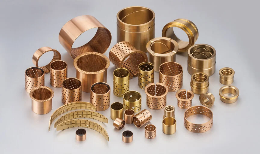
- Can they move freely (such as sliding bearings)
- Can they be firmly combined (such as the gear shaft pressed into the hub)
- Is it too loose or too tight?
2. Satisfy the performance
Match affects the accuracy, strength, life and operating stability of the entire mechanical system. For example, too large a gap will cause vibration and noise, too small an interference will make assembly difficult or damaged parts.
Related Terms of Tolerance
During the machining process, it is impossible to machine the dimensions of parts with absolute accuracy due to the influence of machine tool accuracy, tool wear, measurement errors, etc. In order to ensure interchangeability, the machining error of part dimensions must be limited to a certain range, and the amount of dimensional variation must be specified.
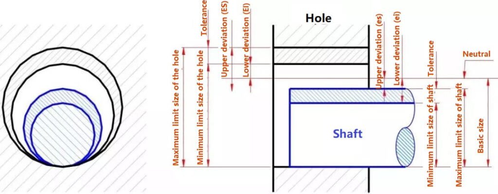
1) Basic size is the size determined during design according to the strength and structural requirements of the part.
2) The actual size is the size obtained by measurement.
3) The limit size allows two limit values for size variation. It is determined based on the basic size. The larger of the two limit values is called the maximum limit size, the smaller one is called the minimum limit size.
4) Dimension deviation (abbreviated as deviation) is the algebraic difference between a certain size and its basic size.
Dimension deviations are:
upper deviation = maximum limit size – basic size
lower deviation = minimum limit size – basic size
upper and lower deviations are collectively referred to as limit deviations, which can be positive, negative or zero.
National standards stipulate that the upper deviation code of the hole is ES, the lower deviation code of the hole is EI, the upper deviation code of the shaft is es, and the lower deviation code of the shaft is ei.
5) Dimensional tolerance (abbreviated as tolerance)
The amount of variation in the allowed dimension.
Dimensional tolerance = maximum limit dimension – minimum limit dimension
= upper deviation – lower deviation
Because the maximum limit dimension is always greater than the minimum limit dimension, that is, the upper deviation is always greater than the lower deviation, the dimensional tolerance must be a positive value.
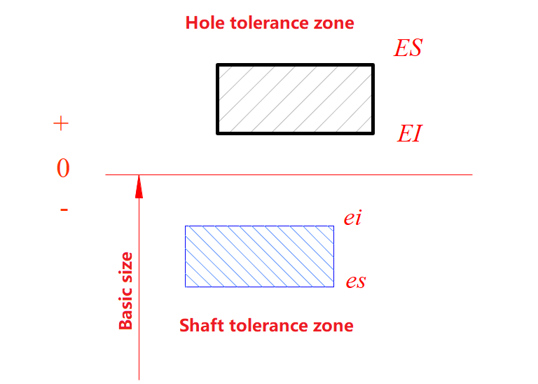
6) Zero line, tolerance zone and tolerance zone diagram
The zero line is a reference line used to determine the deviation in the tolerance zone diagram, that is, the zero deviation line. Usually, the zero line represents the basic dimension. Mark the “0”, “+” and “-” signs on the left end of the zero line. The deviation above the zero line is positive, the deviation below the zero line is negative. The tolerance zone is an area defined by two straight lines representing the upper and lower deviations. The area width and position of the tolerance zone are two elements that constitute the tolerance zone.
7) Standard tolerance and standard tolerance grade
Standard tolerance is any tolerance listed in the national standard to determine the size of the tolerance zone. The standard tolerance grade is the grade that determines the degree of dimensional accuracy. The standard tolerance is divided into 20 levels, namely IT01, IT0, and IT1~IT18, which represent the standard tolerance. Arabic numerals represent the standard tolerance level, among which IT01 is the highest, the levels decrease in sequence, and IT18 is the lowest. For a certain basic size, the higher the standard tolerance level, the smaller the standard tolerance value, and the higher the accuracy of the size.
8) Basic deviation
Basic deviation is used to determine the upper or lower deviation of the tolerance zone relative to the zero line. Generally refers to the deviation close to the zero line. When the tolerance zone is above the zero line, its basic deviation is the lower deviation, and when the tolerance zone is below the zero line, its basic deviation is the upper deviation.
According to actual needs, the national standard stipulates 28 different basic deviations for holes and shafts, respectively, as shown in the figure below. The basic deviation values of holes and shafts can be found in the relevant tables.
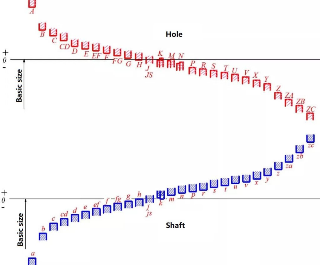
From the above figure, we can see that:
1) The basic deviation code is represented by Latin letters, the basic deviation code is represented by capital letters, and the basic deviation code of the shaft is represented by lowercase letters. Since the basic deviation in the figure only represents the size of the tolerance zone, one end of the tolerance zone is drawn as an open.
2) The basic deviation from A to H is the lower deviation, J to ZC is the upper deviation, and the upper and lower deviations of JS are +IT/2 and -IT/2, respectively.
3) The basic deviation of the shaft is from a to has the upper deviation, j to zc is the lower deviation, and the upper and lower deviations of js are +IT/2T and -IT/2, respectively. Another deviation of the hole and the shaft can be calculated from the basic deviation and the standard tolerance.
Terms Related to Fit
In machine assembly, the relationship between the tolerance zones of holes and shafts that have the same basic dimensions and fit together is called fit. Due to the different actual dimensions of the hole and shaft, “clearance” or “interference” may occur after assembly. In the fit between the hole and the shaft, a positive algebraic difference between the hole size and the shaft size is a clearance, and a negative algebraic difference is an interference.
1. Types of fit
Fits are divided into three categories according to whether they have clearance or interference:
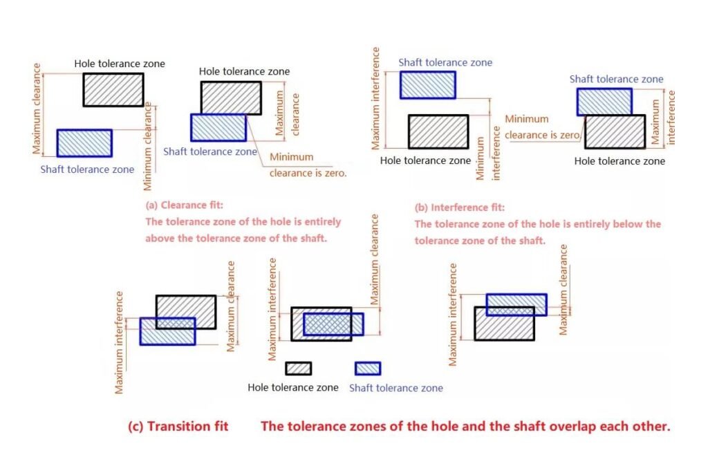
1) Clearance fit
The tolerance zone of the hole is above the tolerance zone of the shaft. Any pair of holes and shafts that match each other will have a clearance fit (including a minimum clearance of zero), as shown in Figure a above.
2) Interference fit
The tolerance zone of the hole is below the tolerance zone of the shaft. Any pair of holes and shafts that match each other will have an interference fit (including a minimum clearance of zero), as shown in Figure b above.
3) Overfit
The tolerance zones of the hole overlap the tolerance zones of the shaft. Any pair of holes and shafts that match each other may have a clearance fit or an interference fit, as shown in Figure c above.
2. Reference system of fit
The national standard stipulates two reference systems, as shown in the figure below.
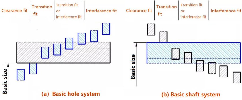
1) Basic hole
The tolerance zone of a hole with a certain basic deviation and the tolerance zone of a shaft with a basic deviation constitute a system of matching, as shown in Figure A. That is, in the matching with the same basic size, the position of the tolerance zone of the hole is fixed, and different matching is obtained by changing the position of the tolerance zone of the shaft. The hole of the basic hole system is called the reference hole. The national standard stipulates that the lower deviation of the reference hole is zero, and “H” is the basic deviation code of the reference hole.
2) Basic shaft
The tolerance zone of a shaft with a certain basic deviation and the tolerance zone of a hole with different basic deviations constitute a system of matching, as shown in Figure B. That is, in the matching with the same basic size, the position of the tolerance zone of the shaft is fixed, and different matching is obtained by changing the position of the tolerance zone of the hole. The hole of the basic shaft center system is called the reference shaft sleeve. The national standard stipulates that the upper deviation of the reference shaft is zero, and “h” is the basic deviation code of the reference shaft.
It can be seen from the basic deviation series diagram:
In the basic hole system, the reference hole H is matched with the shaft, a~h (a total of 11 types) are used for clearance fit, j~n (a total of 5 types) are mainly used for overfit, (n, p, r may be overfit or interference fit), p~zc (a total of 12 types) are mainly used for interference fit.
In the basic shaft system, the reference shaft h is matched with the hole, A~H (a total of 11 types) are used for clearance fit, J~N (a total of 5 types) are mainly used for overfit, (N, P, R may be overfit or interference fit), P~ZC (a total of 12 types) are mainly used for interference fit.
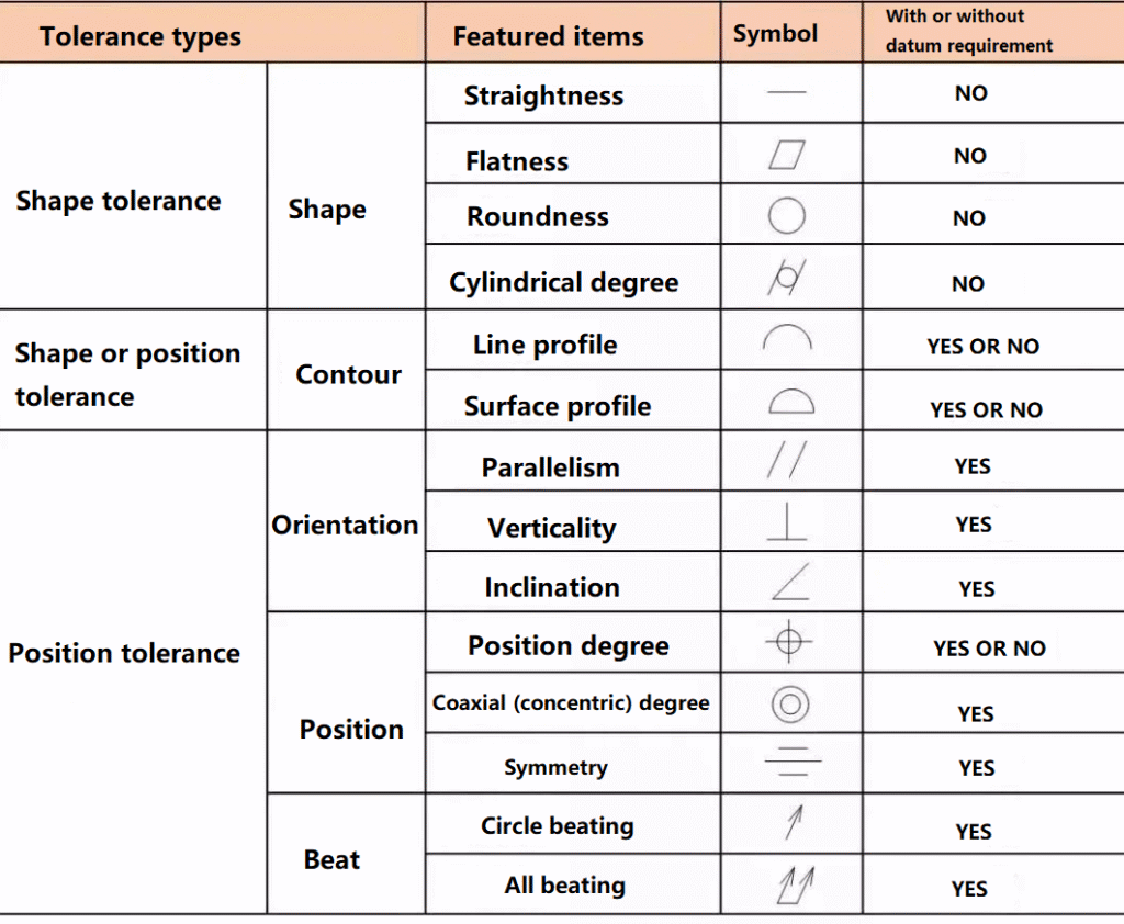
Shape Tolerance
The shape tolerance refers to the total amount of variation allowed in the shape of a single actual element. The shape tolerance is expressed by a shape tolerance zone. The shape tolerance zone includes four elements: shape, direction, position and size of the tolerance zone. The shape tolerance items are straightness, flatness, roundness, cylindricity, line profile, surface profile and other 6 items.
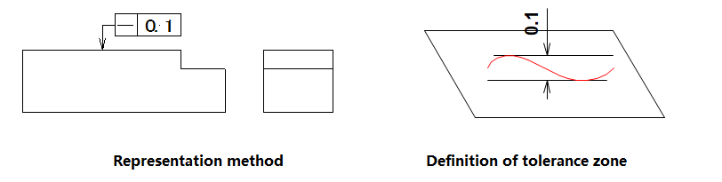
1) Straightness
Straightness is the condition that the actual shape of the straight line element on the part remains an ideal straight line. It is also commonly referred to as the degree of straightness. The straightness tolerance is the maximum variation allowed for the actual line to the ideal straight line. That is, it is given on the drawing to limit the range of variation allowed for the actual line processing error.
2) Planarity
Planarity is the actual shape of the plane elements of the part and maintains the ideal plane. That is what is commonly known as the level of flatness. The planarity tolerance is the maximum amount of change allowed by the actual surface to the plane. That is, given the pattern, to limit the range of variation allowed by actual surface processing errors.
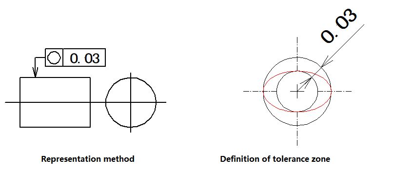
3) Roundness
Roundness represents the actual shape of the element of the circle on the part and is equidistant from its center. That is, what is commonly referred to as the degree of roundness. The roundness tolerance is the maximum amount of change allowed by the actual circle to the ideal circle on the same section. That is, given in the drawing, it is used to limit the range of variation allowed by the processing error of the actual circle.
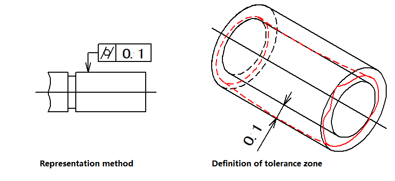
4) Cylindrical degree
Cylindricality represents the points on the outline of the cylindrical surface on the part, and the axis is equidistant. The cylindrical tolerance is the maximum amount of change allowed by the actual cylinder to face the ideal cylindrical surface. That is, given in the drawing, it is used to limit the range of variation allowed by the actual cylindrical processing error.
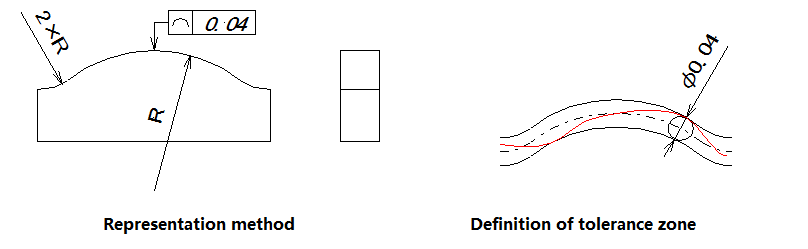
5) Line profile
Line profile is a condition that indicates a curve of any shape on a given plane of a part, maintaining its ideal shape. Line profile tolerance refers to the allowable amount of variation of the actual profile of a non-circular curve. That is, given in the drawing, it is used to limit the range of variation allowed by the actual curve processing error.
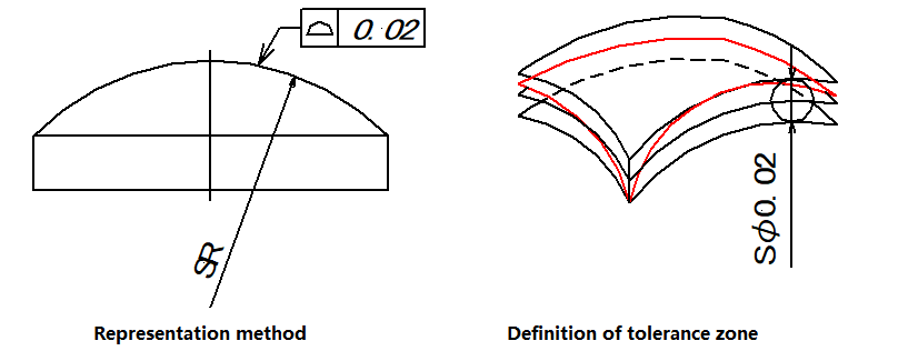
6) Surface profile
The surface profile is a condition that indicates the curved surface of any shape on the part and maintains its ideal shape. The surface profile tolerance refers to the actual contour line of a non-circular curved surface, which allows for the amount of change of the ideal contour surface. That is, given in the drawing, it is used to limit the range of variation of actual surface processing errors.
Position Tolerance
Position tolerance refers to the total amount of changes allowed by the position of the associated actual element to the reference.
(1) Orienteering Tolerance
Directional tolerance refers to the total amount of changes allowed by the associated actual elements to the reference in the direction. This type of tolerance includes three items: parallelism, perpendicularity, and inclination.
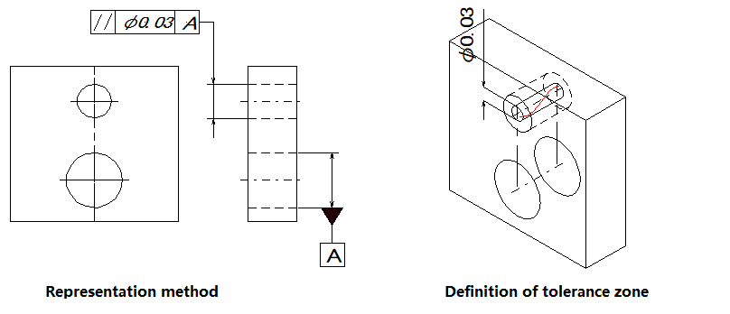
1) Parallelism
Parallelism, which is commonly referred to as the degree to which parallelism is maintained, represents the condition that the actual elements being measured on the part are kept at an equal distance relative to the reference. The parallelism tolerance is the maximum allowable amount of change between the actual direction of the measured element and the ideal direction parallel to the reference.
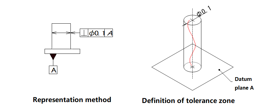
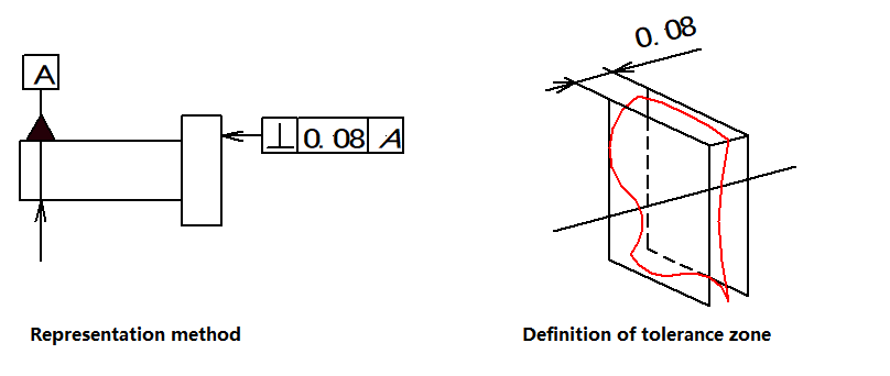
2) Verticality
Verticality, which is usually referred to as the degree to which the two elements remain orthogonal, means that the measured element on the part maintains a correct 90° angle relative to the reference element. The perpendicular tolerance is the maximum amount of change allowed between the actual direction of the measured element and the ideal direction perpendicular to the reference phase.
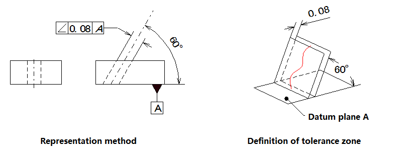
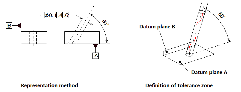
3) Inclination
The inclination is the correct state in which the two elements on the part maintain an arbitrary given angle in the opposite direction. The inclination tolerance is the maximum amount of change allowed between the actual direction of the measured element and the ideal direction for the reference to an arbitrary given angle.
(2) Positioning tolerance
Positioning tolerance is the full amount of change allowed by the actual element to the reference position. This type of tolerance includes three terms: position degree, coaxial degree, and symmetry.
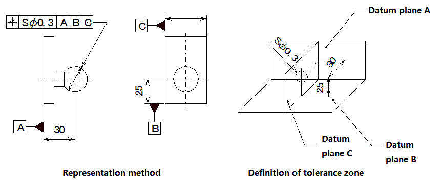
1) Position degree
Position degree represents the accuracy of the points, lines, surfaces and other elements on the part relative to their ideal position. The position tolerance is the maximum amount of change allowed by the actual position of the measured element relative to the ideal position.
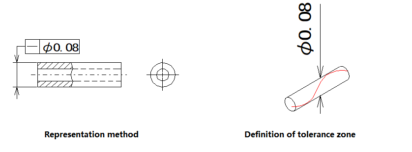
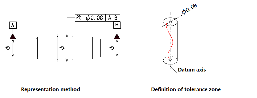
2) Coaxiality
The coaxial degree, which is commonly referred to as the coaxial degree, indicates the condition that the measured axis on the part is maintained on the same straight line relative to the reference axis. The coaxial tolerance is the amount of change allowed by the actual axis to be measured relative to the reference axis.
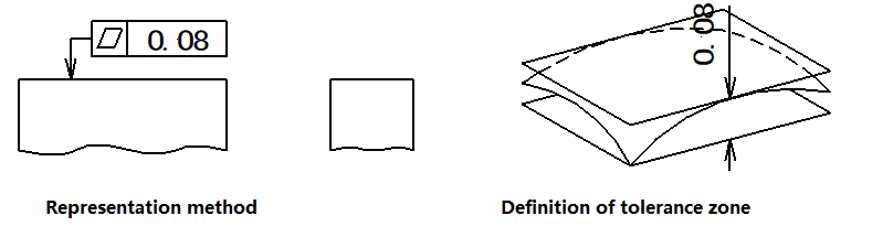
3) Symmetry
Symmetry indicates the state in which two symmetrical center elements on the part remain in the same central plane. Symmetry tolerance is the amount of change allowed by the symmetric center surface (or center line, axis) of the actual element to the ideal symmetry plane.
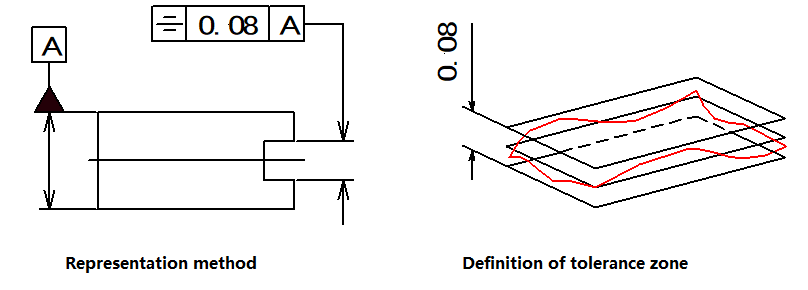
▲Drawing Description: The tolerance band is an area between two parallel planes or between straight lines with a distance of 0.08mm and is symmetrically configured with reference to the reference center plane or center line.
(3) Jump tolerance
A jump tolerance is a tolerance item given based on a specific detection method. The jump tolerance can be divided into circular jump and total jump.
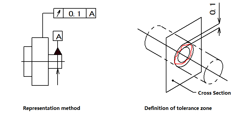
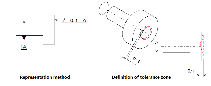
1) Circle jump
Circular pulsation means that the rotating surface on the part is in a defined measurement plane and is maintained in a fixed position relative to the reference axis. The circular jump tolerance is the maximum amount of change allowed within the defined measurement range when the actual element being measured rotates for a full circle without axial movement around the reference axis.
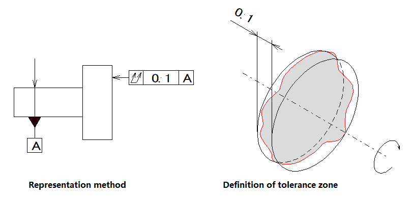
2) Full beating
Full jump refers to the amount of jumping along the entire measured surface when the part rotates continuously about the reference axis. The total jump tolerance is the maximum amount of jump allowed when the actual element being measured rotates continuously about the reference axis while the indicator moves relative to its ideal profile.
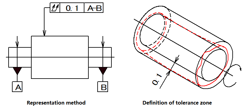
▲Drawing Description 1: The tolerance zone is the area between two cylindrical surfaces with a distance of 0.1mm and coaxial to the reference.
Tolerance Type