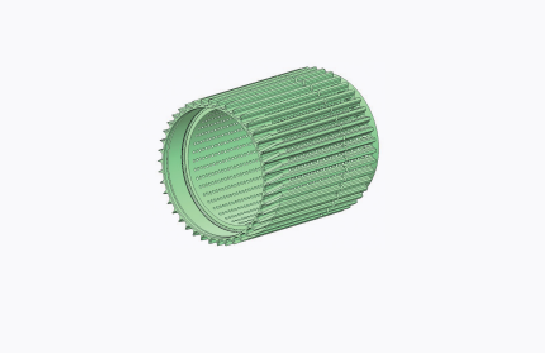
The drum wheel part is an aluminum alloy thin-walled long cylinder structure with irregular long grooves and mesh-like circular holes evenly distributed around it. The amount of material removed is large, and the processing deformation is difficult to control. The quality problems are mainly concentrated on the inner hole and outer circle deviation caused by deformation.
Through process optimization, this article changes the fine boring process from the tooling embracing radial clamping to the vertical clamping axial clamping. During the clamping process, the micrometer is used to measure the changes in the inner hole and the displacement of the generatrix on the outer circle side, and the deformation is monitored throughout the process. The problem of part deformation during the processing process is solved by controlling the processing allowance, removing processing stress, and reserving surface treatment process dimensions.
The drum wheel is a key part of the filter rod output system of the filter rod forming unit. It cooperates with the valve body, valve seat and other parts assembled inside to use negative pressure to slow down and calibrate the filter rod and transmit it downstream, playing an important role as a transportation hub.
Table of Contents
Part Structure and Technical Requirements
The drum wheel part is an aluminum alloy thin-walled long cylinder structure (see Figure 1). The key dimensions are shown in Figure 2, where the dimension band * requires no surface and the dimension band ** is the final dimension after surface treatment. There are 42 special-shaped long grooves and 966 φ5mm holes evenly distributed around the part. The metal removal rate during processing reaches 82.5%, and the part has poor rigidity. Because the long grooves around the part are filter rod channels, in order to improve the surface wear resistance, the surface of the part requires local hard anodizing treatment (Al/Et.A50hd) and local spraying of LW-1N10, with a coating thickness of (0.06±0.02) mm. During the early trial production, it was found that the key dimensions of the part φ195H7 hole, φ215H6 hole and φ218f7 outer circle were very easy to deform during processing, and the trial production qualification rate was 0%.

Problems in Processing
During the trial production, a total of 11 pieces were put into production. The process flow is: the rough turning of the outer circle, inner hole and end face → stress relief → semi-finishing turning of outer circle and inner hole → rough milling of long slots and drilling → fine boring of holes and end faces → fine turning of outer circle → fine milling of slots → anodizing → spraying.
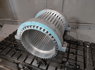
The acceptance rate of the trial production was 0%. The quality problems were mainly the out-of-tolerance of φ195H7 hole, φ215H6 hole and φ218f7 outer circle. According to the whole process processing plan of the drum wheel, the clamping method of fine boring is the special tooling embracing radial clamping, as shown in Figure 3. This clamping method is not suitable for fine boring of thin-walled parts. It will cause slight deformation of the hole when clamping. After boring, the clamp is released and the part rebounds, resulting in out-of-tolerance hole roundness. It was found through testing that the roundness of the φ215H6 hole after precision boring was 0.04mm, which was out of tolerance. At the same time, the spray paint was sprayed onto the surface of the part at a temperature of about 160°C, causing the stress inside the part to be released. It was found through testing that the roundness of the hole changed by 0.02mm during the spraying process.
Process Plan Optimization
In view of the defects of the trial production process plan, in order to avoid the deformation of the part during the fine boring clamping, the clamping method was changed from the tooling embracing radial clamping to the vertical clamping axial clamping. The three equal-height blocks were fixed on the universal fixture base plate, the part was positioned with the φ218f7 outer circle end face, and the step pressure plate was placed in the groove with a circumferential width of 5mm for the part to be clamped. During the clamping process, the micrometer was used to measure the changes in the inner hole and the displacement of the generatrix on the outer circle side. By adjusting the clamping force of each pressure plate, the deformation displacement of the part before and after clamping was ensured to be ≤0.01mm, as shown in Figure 4. After verifying that the deformation of the vertical clamping method is controllable, the fine boring trial processing was carried out on the Makino V77L vertical machining center, and the hole deformation was monitored throughout the process. The specific data is shown in Table 1. After testing, the roundness of the hole after processing is ≤0.015mm, which meets the requirements.
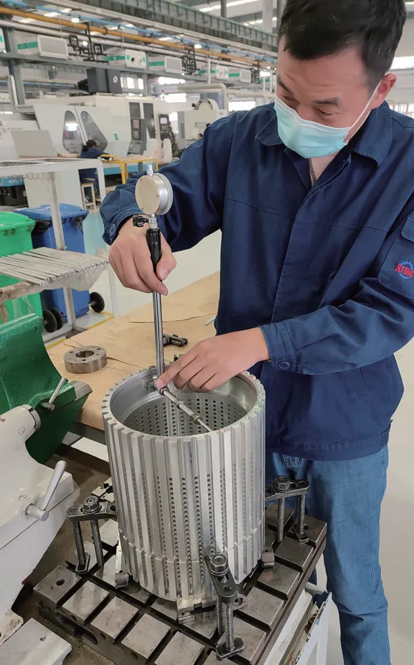
Table 1 Deformation of φ215H6 in vertical clamping mode (unit mm)
| Measurement position | Free state | After pressing | After boring (pressing) | After boring (free) | After boring Leave for 24 hours |
| 0° | -0.18 | -0.18/ -0.17 | +0.02 | +0.015 | +0.015 |
| 45° | -0.19 | -0.19/ -0.18 | +0.02 | +0.025 | +0.025 |
| 90° | -0.20 | -0.20 | +0.02 | +0.020 | +0.020 |
| 135° | -0.19 | -0.20/ -0.19 | +0.02 | +0.020 | +0.025 |
Due to the large amount of blank removal, thin wall and multiple holes and grooves, the parts are deformed due to changes in internal stress during processing. If the processing stress is not removed in the early stage, the stress will be released during the anodizing and spraying process, thereby increasing the deformation of the parts. Therefore, eliminating the deformation caused by processing stress is very important for improving the processing accuracy of drum parts.
In order to reduce the influence of anodizing and spraying on the deformation of parts and minimize the internal stress of parts, two stabilization treatments were added on the basis of the original process stabilization treatment. That is, three stabilization treatments were performed. The finishing part was changed from the previous fine boring → fine turning of the outer circle → fine milling of the groove → anodizing → spraying to horizontal rough boring to remove the allowance → stabilization treatment → vertical semi-finishing boring with allowance to φ194.5mm and φ214.5mm → fine turning of the outer circle → fine milling of the groove → vertical fine boring → anodizing → spraying. The specific process plan is shown in Table 2.
Table 2 Drum wheel processing optimization process plan
| Process No. | Process | Work Center | Operation Details |
|---|---|---|---|
| 10 | Turning | HT690 | Rough turn outer diameter to Ø245 mm, overall length to 320 mm, rough bore to Ø190 mm, chamfer bore opening at 60°. |
| 20 | Heat Treatment | QYL | Stress relief treatment. |
| 30 | Turning | HT690 | Use fixture C with double centers for turning, turn outer diameter to 244 mm. |
| 40 | Milling | A82 | Use fixture T1 with outer diameter positioning, mill right end face leaving 1 mm stock, bore Ø195H7 hole to Ø192H7 (positioning section about 30 mm from right end, rest free tolerance), chamfer bore opening, drill and ream two M8 and three M6 tapped holes on right end face, tap threads, drill and ream Ø6H7 dowel holes, X/Y distance to large hole center (72.8 ± 0.01) mm, mill left end face leaving 1 mm stock, mill total length to (298 ± 0.1) mm, bore left step hole to Ø212H7, leave 2 mm stock on right side. |
| 50 | Turning | HT690 | Use fixture C1 positioned by both end holes and right end face, turn outer diameter to 242 mm. |
| 60 | Milling | V77L | Use fixture X1 positioned by both end holes and dowel hole, rough mill 42 arc slots (leave 1 mm stock on diameter), mill inner long holes and slots, drill 966 holes. |
| 70 | Heat Treatment | WD | Stabilization treatment. |
| 80 | Milling | A82 | (1) Use fixture T1 positioned by outer diameter, align, mill right end face, bore Ø195H7 hole to (194 ± 0.05) mm, chamfer. (2) Flip, align, mill left end face to ensure (296 ± 0.3) mm to 296 mm, bore Ø215H6 and Ø215H8 holes to (214 ± 0.04) mm, bore relief groove, bore Ø208 mm hole to 208.1 mm. |
| 90 | Heat Treatment | WD | Stabilization treatment. |
| 100 | Milling | V77L | Bore Ø195H7 hole to 194.5 mm, Ø215H6 hole to 214.5 mm. |
| 110 | Turning | HT690 | Use fixture C2 positioned by both Ø194.5 mm and Ø214.5 mm holes, align, turn all outer diameters, step faces, and 5 mm wide groove, chamfer. Major outer diameter to 241 mm, Ø218f7 step outer diameter to 218.5 mm, ensure perpendicularity to 72 mm right face <0.015 mm. |
| 120 | Milling | V77L | (1) Use fixture X2 positioned by both end holes, dowel hole, and right end face, finish mill 42 arc slots to Ø8.7~8 mm (surface roughness Ra=1.6 µm) and left end slotted groove and chamfer, control P222.3%mm dimension to P222.3 mm, align M8 threaded holes, drill remaining holes and tapped holes on right end face and step face, chamfer openings, tap threads, mill 3 locations to ensure arc slot requirements, do not tap M4 yet. (2) With Ø218.5 mm outer diameter aligned with 72 mm right step face, align, clamp plates on 5 mm wide groove at 3 evenly spaced points, finish bore Ø195H7 hole to Ø195 mm, Ø215H6 hole to Ø215 mm. |
| 130 | Benchwork | QG | Tap M4 threads, deburr, smooth edges of ten 5 mm wide grooves for smooth transition. |
| 140 | Surface Treatment | YJYH | Al/EtA50hd.cl(BK) hard anodizing (protect threaded holes, control hole and step outer diameter precision), approx. 20 dm² surface area. |
| 150 | Spraying | PD | Use fixture ZY, outsource spraying per technical requirements (protect Ø218 mm outer diameter and holes), prevent scratches, dents, and deformation. |
| 160 | Turning | HT690 | Use fixture C3 with both Ø195H7 and Ø215H6 holes as datum for axial clamping, finish turn Ø218f7 outer diameter, chamfer. |
| 170 | Benchwork | QG | Polish slots. |
Problems in processing
After determining the feasible solution, batch processing verification is carried out according to the new process plan, and key process data are monitored and recorded. The dimension inspection before storage is shown in Figure 5, and some dimension inspection results are shown in Table 3.
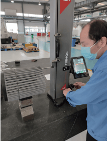
Table 3 Results of partial dimension inspection before storage (Unit mm)
| Test piece number | Design requirements | Hard anodizing | Warehouse inspection after spraying (Temperature 22℃) | |
| Before oxidation | After oxidation | |||
| Test piece No. 1 | Ø215 (+0.029) | +0.05 | +0.005 | +0.01 |
| +0.06 | +0.015 | +0.025 | ||
| Ø195 (+0.046) | +0.06 | +0.02 | +0.03 | |
| +0.07 | +0.04 | +0.045 | ||
| Test piece No. 2 | Ø215(+0.029) | +0.05 | +0.01 | +0.02 |
| +0.05 | +0.015 | +0.02 | ||
| Ø195(+0.046) | +0.08 | +0.03 | +0.03 | |
| +0.07 | +0.03 | +0.04 | ||
The roundness of the parts entering the warehouse is ≤0.02mm, which fully meets the design requirements and is qualified for storage. So far, multiple batches of drum wheel parts have been successfully processed, and all have been qualified for storage.
Conclusion
The design precision of drum wheel parts is high, the material removal is large, and the processing deformation is difficult to control. During the process design process, by improving the clamping method, optimizing the processing allowance control, increasing the heat treatment to remove stress and reserving the surface treatment process size and other measures, the deformation of the parts during the processing is avoided, and the processing quality of the parts is well guaranteed. This process scheme has been promoted and applied to the processing of parts of other specifications and has achieved good results.
The drum wheel part is an aluminum alloy thin-walled long cylinder structure with special-shaped long grooves and mesh round holes evenly distributed around it. The material removal is large, the processing deformation is difficult to control, and the quality problems are mainly concentrated on the inner hole and outer circle tolerance caused by deformation. Ensured the processing quality of the drum wheel by optimizing the process scheme, improving the clamping method, and reasonably arranging heat treatment and local surface treatment.
The highlight of the article is the clamping method and deformation control of thin-walled long cylindrical parts. The process plan and process content are relatively detailed. Through process optimization, the fine boring process is changed from tooling embracing radial clamping to vertical clamping axial clamping. During the clamping process, the micrometer is used to measure the change of the inner hole and the displacement of the outer circle side generatrix, and the deformation is monitored throughout the process. By controlling the processing allowance, removing the processing stress and reserving the surface treatment process size and other measures, the problem of part deformation in the processing process is solved, which has good practicality.
Source: Xie Yangyang. Process Optimization for Precision Thin-Walled Drum Parts Machining. Metal Processing (Cold Working), 2025, No.1: pp. 47–50.

