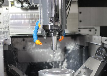
01How to Get High-Quality CNC Metal Parts: A Complete Guide
When you need custom CNC metal parts for a prototype or production run, the quality of the final parts directly determines whether your assembly works, your product passes inspection, or your equipment runs reliably. This guide provides the exact steps, design standards, and supplier evaluation criteria to help you consistently get CNC metal parts that meet your specifications—without guesswork or costly rework.
What This Guide Covers
You will learn:
The three most common reasons CNC metal parts fail inspection
How to specify dimensions, tolerances, and surface finishes correctly
Which design features cause machining problems and how to fix them
A step-by-step supplier qualification checklist
How to verify part quality before and after production
The Three Most Common Quality Failures in CNC Metal Parts
Based on real production data from thousands of machining orders, three issues account for over 80% of rejected CNC metal parts.
1. Dimensionally Incorrect Features
What happens: A hole is drilled 0.5 mm off position, or a shoulder length is 0.2 mm too long. The part does not fit into the mating assembly.
Why it occurs:
Incorrect tool offset calibration on the CNC machine
Thermal expansion of the metal during high-speed cutting
Fixture movement under cutting forces
How to prevent it:
Require your supplier to run a first-article inspection (FAI) per AS9102 or ISO 9001 standards
Specify critical dimensions with geometric dimensioning and tolerancing (GD&T) rather than relying on default machine accuracy
For parts with tolerances of ±0.025 mm or tighter, request CMM (coordinate measuring machine) inspection reports
2. Poor Surface Finish Leading to Functional Failure
What happens: A shaft surface that should be 0.8 µm Ra comes out at 3.2 µm Ra. The seal leaks, or the bearing fails prematurely.
Why it occurs:
Worn cutting tool inserts
Incorrect feed rate or spindle speed for the specific metal alloy
Inadequate coolant flow or wrong coolant type
How to prevent it:
Specify surface finish requirements on your drawing using the standard Ra symbol
For sealing or bearing surfaces, require a profilometer measurement report
Ask for machined samples of the critical surface before full production
3. Burrs and Sharp Edges Not Removed
What happens: Small raised edges remain along the part perimeter after machining. During assembly, the burr prevents the part from seating fully, or a sharp edge cuts a wire or injures an operator.
Why it occurs:
Deburring operation was rushed or omitted
CNC program did not include a spring pass or chamfering operation
Supplier assumed “as-machined” edges are acceptable
How to prevent it:
Explicitly state edge break requirements (e.g., “break all edges 0.1–0.3 mm”)
Specify maximum allowable burr height, typically 0.05 mm for precision parts
For safety-critical edges,require thermal or vibratory deburring
How to Specify CNC Metal Parts Correctly
Every complete specification for CNC metal parts must include five elements. Missing any one of them is the leading cause of receiving wrong parts.
Element 1: Material Grade and Condition
Do not write “aluminum” or “stainless steel.” Write the exact grade and temper.
Correct examples:
Aluminum 6061-T6
Stainless steel 303, annealed per ASTM A582
Brass C36000, half-hard
Steel 4140, pre-hardened to 28–32 HRC
Why this matters: Different tempers machine differently and have different as-machined surface finishes. Using the wrong temper can double cycle time or make tight tolerances impossible to hold.
Element 2: Fully Defined Dimensions
Every feature must have a dimension or be controlled by a general tolerance note.
Minimum required:
Overall length, width, and height
Hole diameters and depths
Hole-to-hole center distances
Thread specifications (size, class, depth)
General tolerance note example (place in drawing title block):
“UNLESS OTHERWISE SPECIFIED: DIMENSIONS ±0.13 mm, ANGLES ±1°”
For ISO-standard drawings, reference ISO 2768-mK as the default.
Element 3: Tolerances on Critical Features
Tolerance determines cost more than any other single factor. Only tighten tolerances on features that truly need them.
Standard cost guideline:
±0.125 mm: Standard machining tolerance, no added cost
±0.050 mm: Requires careful setup, 20–30% cost increase
±0.013 mm: Requires grinding or fine boring, 100–200% cost increase
±0.005 mm: Requires jig grinding or lapping, 300%+ cost increase
Actionable advice: Review your design and identify which dimensions actually affect fit, function, or interchangeability. Loosen all others to ±0.125 mm or ±0.010 inch.
Element 4: Surface Finish Requirements
Use the standard Ra (roughness average) symbol. If no surface finish is specified, the supplier will deliver “as-machined” finish, which typically ranges from 1.6 to 3.2 µm Ra.
Common finish values and applications:
Element 5: Inspection and Reporting Requirements
State clearly what quality documentation you require.
Three standard levels:
1. Certificate of conformance (C of C): Supplier certifies parts meet drawing requirements. No measurement data provided.
2. First-article inspection (FAI) report: Full dimensional report on the first part produced. Required for new parts or after engineering changes.
3. Full inspection report: Every part measured on critical dimensions. Used for high-reliability applications.
For most production parts, a C of C plus an FAI is the standard requirement.
Design for Manufacturability: What to Avoid
Certain design features make CNC metal parts unnecessarily expensive or impossible to produce. The following five issues account for most design-related delays.
Avoid Deep Pockets with Square Inside Corners
Problem: A standard end mill is round. When it machines a pocket, the inside corners will have a radius equal to the cutter diameter. A square inside corner cannot be machined without EDM or a secondary operation.
Solution: Specify a corner radius at least 1 mm or larger. For blind pockets, keep depth less than four times the cutter diameter. For a 6 mm end mill, maximum practical depth is 24 mm.
Avoid Threads That Go to the Bottom of a Blind Hole
Problem: A taper at the bottom of a drilled hole prevents the tap from cutting threads all the way to the bottom.
Solution: Specify a minimum thread depth of three diameters for engagement strength. Leave at least 0.5 diameter of unthreaded length at the bottom of the hole.
Avoid Thin Walls
Problem: Walls thinner than 1 mm in metal parts vibrate during cutting, causing poor surface finish and inaccurate dimensions.
Solution: Design walls at 1.5 mm minimum for aluminum, 2 mm for steel. If thin walls are unavoidable, specify a support fixture or wire EDM as the machining method.
Avoid Extremely Tight Tolerances on Non-Critical Features
Problem: A non-functional boss dimension toleranced to ±0.013 mm forces the supplier to use slower machining strategies, increasing cost without any benefit.
Solution: Review every tolerance. Ask: “Does this feature actually need this precision?” If not, change it to ±0.125 mm.
Avoid Undercuts Without Specifying Radius
Problem: An undercut is a recessed feature that requires a specially ground tool. Without a radius specified, the supplier must guess.
Solution: Always specify the undercut radius and width. Standard values are 0.5 mm or 1 mm radius.
Supplier Qualification Checklist
Before placing an order for CNC metal parts, verify the following seven items. A common mistake is to assume all CNC shops have the same capabilities—they do not.
1. Machine Capability
What is the maximum part size the CNC mills and lathes can handle?
What is the stated positioning accuracy (typically ±0.005 mm for modern machines)?
Does the shop have 3-axis, 4-axis, or 5-axis machining centers?
2. Material Sourcing
Can the supplier provide material certifications (mill test reports) per EN 10204 3.1?
Do they stock common alloys or require you to supply material?
3. Inspection Equipment
Does the shop have a calibrated CMM (coordinate measuring machine)?
Are surface profilometers available for finish measurements?
When was the last calibration of all inspection tools?
4. Quality System Certification
ISO 9001:2015 is the minimum standard for a reliable supplier.
AS9100D is required for aerospace applications.
IATF 16949 is required for automotive production parts.
5. Secondary Operations
Does the shop perform deburring, heat treatment, anodizing, or plating in-house?
If not, which subcontractors do they use?
Ask for examples of finished parts with similar secondary operations.
6. Lead Time and Batch Size
What is the typical lead time for a first article? For production?
Is there a minimum order quantity?
What is the cost break for different batch sizes (e.g., 1, 10, 50, 100 pieces)?
7. Communication and Documentation
Does the supplier provide inspection reports in a standard format (Excel, PDF, or paper)?
Is there a single point of contact for technical questions?
Will they review your drawing before quoting to flag potential issues?
How to Verify Part Quality: Step-by-Step
Follow this verification process for every new CNC metal part, regardless of the supplier’s reputation.
Step 1: Drawing Review Before Ordering
Send your drawing to the supplier and explicitly ask: “Please review this drawing for any features that cannot be machined as shown, or any tolerances that conflict with standard machine capability.”
A qualified supplier will respond with specific questions or proposed changes. A red flag is receiving a quote with no comments on a complex drawing.
Step 2: First-Article Inspection
For the first production run, request a first-article inspection report. This report must include:
Actual measured dimensions for every feature on the drawing
Measured surface finish on critical surfaces
Material certification
Photographs of the actual part
Do not approve full production until you have reviewed the first-article report and confirmed the parts meet your requirements.
Step 3: Incoming Inspection on First Shipment
When the parts arrive, perform your own inspection on at least three parts from the shipment. Measure:
Three to five critical dimensions that affect fit
Visual inspection for burrs, scratches, and surface finish
Thread gauge check if threads are specified
If the incoming inspection matches the supplier’s first-article report, you have high confidence in ongoing quality. If there are discrepancies, request a joint measurement review.
Step 4: Functional Testing
Install the CNC metal parts into your assembly and test under actual operating conditions. For example, if the part is a housing, assemble it with mating parts and check for proper fit. If it is a shaft, run it at operating speed and temperature.
Document any issues such as binding, leakage, or excessive wear. Provide this feedback to your supplier to improve future batches.
Common Questions About CNC Metal Parts
What is the typical tolerance for standard CNC machining?
For a well-maintained CNC mill or lathe, standard machining tolerance is ±0.125 mm (±0.005 inch) for metal parts. Tighter tolerances are possible but require slower machining speeds, special tooling, or additional finishing operations.
Can I get a quote for just one prototype part?
Yes. Most CNC machine shops accept single-piece orders. Expect a higher per-part cost because setup time is the same for one part as for 100 parts. Typical setup fees range from $100 to $500 depending on part complexity.
Which metal is easiest to machine for tight tolerances?
Brass C360 and aluminum 6061 are the most machinable metals. They produce fine chips, do not work-harden, and hold tight tolerances reliably. Stainless steel 303 is also machinable but requires slower speeds.
How do I specify a thread on a CNC metal part?
Use this standard format: “M6 x 1.0 – 6H THRU” for a metric through hole, or “1/4-20 UNC-2B x 12 mm DEEP” for an imperial blind hole. The thread class (6H for metric, 2B for UNC) specifies the fit tolerance.
What surface finish can I expect without specifying?
Without a specified surface finish, the supplier will deliver “as-machined” finish, typically 1.6 to 3.2 µm Ra. Visible tool marks will be present. For smooth or sealing surfaces, you must specify a finish value.
Why do quotes from different suppliers vary so much?
Price differences come from:
Different machine types (3-axis vs 5-axis)
Different tolerance assumptions (standard vs tight)
Different material sourcing (certified vs uncertified)
Different included services (deburring vs no deburring)
Always compare quotes line by line for material, tolerances, and included inspection reports.
Actionable Recommendations
To get high-quality CNC metal parts on your next order:
1. Review your drawing before sending it out. Remove unnecessarily tight tolerances. Specify corner radii on pockets. Define surface finishes clearly.
2. Send your drawing to three suppliers. Ask each for a quote and a drawing review. Compare not just price but also the quality of their technical questions.
3. Request a first-article inspection report for every new part. Do not skip this step even for simple parts.
4. Perform incoming inspection on the first shipment. Measure at least three critical dimensions. Confirm surface finish visually and with a profilometer if required.
5. Build a relationship with one or two reliable suppliers. Share your quality requirements clearly. Provide feedback on every order. Over time, they will learn your standards and deliver consistently.
Following these steps will reduce rework, eliminate surprise costs, and ensure that every CNC metal part you receive works the first time you install it.