CNC Milling is an efficient, flexible and widely used processing method, suitable for everything from rough machining to precision parts molding. Whether you are a mechanical engineer, CNC programmer, or a practitioner in the manufacturing field, an in-depth understanding of different milling processing methods, processing strategies and key calculation formulas will help improve processing efficiency, improve surface quality, and achieve higher dimensional accuracy. This article will systematically sort out the main methods, typical processing strategies, and commonly used calculation formulas of milling to provide a practical reference for your processing projects.
Table of Contents
1) Basic milling processes include plane milling, slot milling, side milling, and profile milling.
Plane Milling
Plane milling is primarily used to machine the top surface of a workpiece, producing a flat and smooth finish. This operation typically involves a face mill or a tool equipped with multiple indexable inserts.
Key Characteristics:
- Cutting Mechanism: The end teeth (bottom edge) of the tool are primarily responsible for cutting, while the peripheral edges may assist in the process.
- Machining Purpose: Suitable for both roughing and finishing large surface areas, providing high material removal rates and good surface quality.
Tool Engagement Features:
Large Radial Width of Cut (ae): A wider engagement along the workpiece width enhances efficiency by covering more area per pass.
Small Axial Depth of Cut (ap): A shallow ap helps reduce tool load and improves cutting stability.
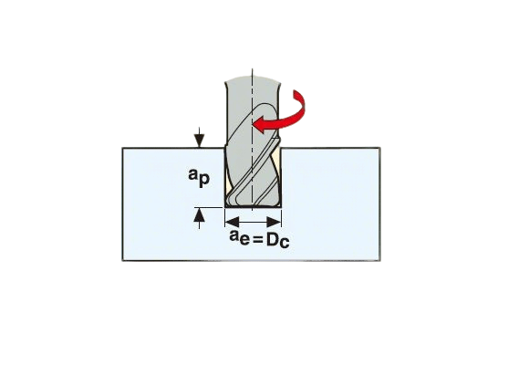
Slot Milling
Slot milling involves full-width engagement of the tool to create slots or grooves in the workpiece. This method typically uses an end mill, and it demands careful parameter selection to maintain tool life and cutting stability.
Key Characteristics:
- Full Tool Engagement: The tool’s diameter (Dc) is fully engaged with the material, meaning the radial width of cut (ae) is equal to Dc.
- Depth of Cut (ap): The axial depth of cut can reach up to 1.5 times the tool diameter, depending on the machine and material conditions.
- Dc Selection: The diameter of the cutter (Dc) is chosen based on the specific milling strategy being applied — for example, slotting in a single pass or using multiple step-downs.
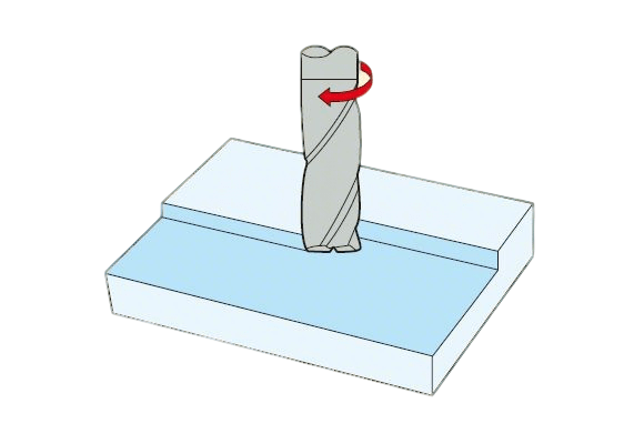
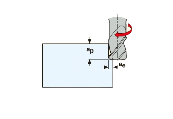
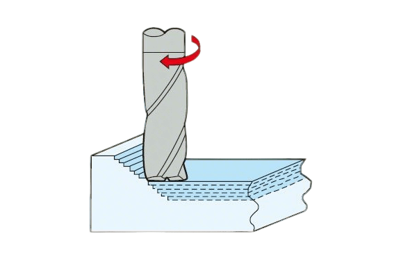
Side milling
Side milling involves cutting along the side of the tool, engaging primarily the peripheral edges to machine vertical or contoured surfaces on the workpiece.
Key Characteristics:
Side Engagement: Material is removed through the lateral edges of the cutter, making it ideal for profiling, contouring, or machining steps and vertical walls.
Cutting Parameters:
- Large axial depth of cut (ap): Enables deeper engagement along the vertical direction, increasing material removal per pass.
- Small radial width of cut (ae): Typically narrower, providing better control and reducing tool deflection.
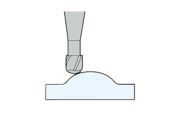
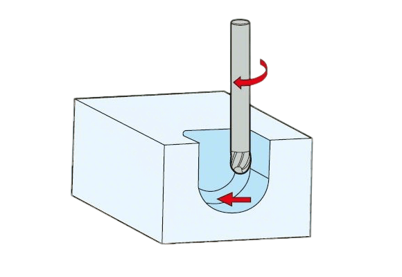
Profile Milling
Contour milling—also known as profile milling—is used to machine complex 3D surfaces or curved profiles, often seen in mold making, aerospace, and precision parts.
Key Characteristics:
Tool Engagement: The ball-nose tip of the tool engages with the workpiece, allowing for smooth surface transitions on contoured geometries.
Cutting Parameters:
- Small axial depth of cut (ap): Ensures precision and reduces tool pressure when working with fine details.
- Small radial width of cut (ae): Helps maintain surface finish and avoids tool chatter, especially on curved paths.
2) Advanced milling processing
Including: ramp milling, helical ramp milling, trochoidal milling, push-pull contour milling, plunge milling, contour milling, drilling.
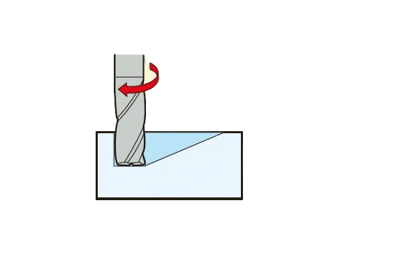
Ramp Milling
Ramp milling is a technique used to enter a pocket or cavity by moving the tool at an inclined angle along the Z-axis, rather than plunging vertically.
Key Characteristics:
Tool Path: The cutter moves along a sloped or helical path, gradually descending into the material. This reduces tool load compared to direct plunging.
Application: Commonly used for pocket milling, especially when drilling a pilot hole is not feasible or when using end mills without center cutting capability.
Advantages:
Improved tool life due to reduced entry shock
Enhanced chip evacuation
Greater flexibility in toolpath generation
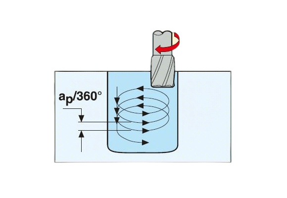
Helical Ramp Milling
Helical ramp milling is an advanced entry strategy where the tool performs a circular (helical) motion while simultaneously moving downward along the Z-axis to enter a cavity or pocket.
Key Characteristics:
Tool Path: The cutter follows a helical trajectory, combining both radial (circular) and axial (Z-axis) movements to gradually descend into the material.
Application: Ideal for closed pockets or when using end mills that lack center-cutting capability.
Advantages:
- Smooth engagement with the material
- Reduced axial load compared to vertical plunging
- Better chip evacuation and heat dissipation
- Less tool wear and vibration
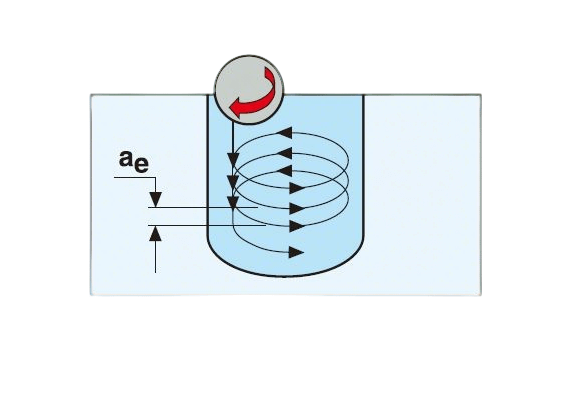
Trochoidal Milling
Trochoidal milling is a high-efficiency slotting technique in which the tool performs partial circular motions along the X or Y axis, effectively turning a slotting operation into a side milling process.
Key Characteristics:
Tool Path: The cutter follows a trochoidal (cycloidal) path, repeatedly entering and exiting the material in arcs, rather than engaging the full slot width at once.
Cutting Strategy: Uses the side edges of the tool for material removal, minimizing radial engagement and reducing cutting forces.
Purpose: Converts a traditional slotting operation into a more efficient side milling approach, ideal for harder materials or deep slots.
Advantages:
- Lower tool load and heat buildup
- Improved chip evacuation
- Extended tool life
- Allows higher feed rates and speeds
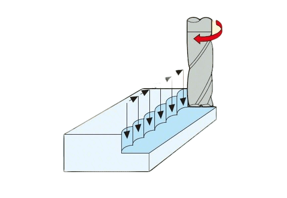
Push-Pull Contour Milling
Push-pull contour milling is a 3D machining technique in which the tool follows the contour of a complex surface by moving up and down along the Z-axis while simultaneously tracking the surface profile in the X-Y plane.
Key Characteristics:
- Tool Path: The cutter performs a continuous up-and-down profiling motion along the 3D surface, effectively replicating the shape of the model.
- Application: Commonly used for freeform surfaces, such as molds, dies, turbine blades, and automotive body components.
- Machining Style: This method emphasizes consistent tool contact with the surface, maintaining a uniform scallop height and better surface finish.
Advantages:
- High surface accuracy on complex geometries
- Better control over surface quality
- Reduced need for secondary finishing
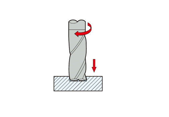
Plunge Milling
Plunge milling is a method in which the tool moves vertically along the Z-axis, similar to drilling, to remove material and create deep grooves or cavities.
Key Characteristics:
- Tool Movement: The cutter plunges straight down into the workpiece in axial steps, rather than moving laterally.
- Application: Often used for roughing deep pockets, hard materials, or difficult-to-machine areas where side cutting is less effective.
- Tool Type: Typically performed with specialized end mills or indexable insert cutters capable of center cutting.
Advantages:
- Reduced radial cutting forces
- Improved stability in deep or narrow cavities
- Effective chip evacuation when combined with coolant
Z-Level (Constant Z) Contour Milling
Z-level contour milling, also known as constant Z milling, involves generating a 3D surface by machining in layers at fixed Z heights, combining slight Z-axis movement (via plunging or ramping) with contour following in the X and Y axes.
Key Characteristics:
- Machining Strategy:
- Begins with a small step-down in the Z direction (either through plunge or ramp).
- Follows the surface contour in X and Y at each level before descending to the next Z level.
- Application: Ideal for complex 3D geometries such as mold cavities, dies, and sculpted surfaces with vertical or semi-vertical walls.
Advantages:
- Maintains consistent scallop height on steep areas
- Produces high-quality finishes on contoured surfaces
- Easy to control tool engagement and chip load
Drilling
Drilling is a fundamental machining process in which the tool moves along the Z-axis to create a cylindrical hole in the workpiece.
Key Characteristics:
- Tool Movement: The drill bit advances linearly in the Z direction, cutting material to form a hole.
- Application: Suitable for through holes, blind holes, and preparation for tapping or boring operations.
- Tool Type: Typically performed with twist drills, though other types like center drills or spot drills may be used for positioning.
Advantages:
- Fast and efficient hole-making process
- Simple setup and operation
- Compatible with most materials
Definition of Milling Processing Strategy
(1) General machining
It is a general-purpose machining strategy. The ratio of cutting width to cutting depth can vary, depending on the type of process.
1) Tool characteristics: The tool has a relatively long cutting edge and a small core diameter and does not require high precision.
2) Machine tool requirements: No special requirements.
3) Application areas: Basic CNC technology is required, and advanced machining methods with high difficulty are not feasible; the metal removal rate can only reach a general level; the application areas usually include small batch sizes and a wide range of materials.
(2) High-speed machining
It is a machining strategy that combines the use of a small radial cutting depth, high cutting speed and feed rate; depending on the method used, a high material removal rate and a low Ra value can be achieved. The typical characteristics of this strategy are low cutting force, less heat transferred to the tool and workpiece, reduced burr formation and high dimensional accuracy of the workpiece; under high-speed machining, a faster cutting speed than ordinary machining can achieve a high metal removal rate and good surface roughness.
1) Tool characteristics: stable (large core diameter and short cutting length), clear and well-formed chip space, conducive to good chip evacuation and coating.
2) Machine tool requirements: high-speed CNC control, high speed, fast table feed speed.
3) Application areas: semi-finishing and finishing of hardened steel (48-62 HRC) in the mold industry, with short delivery time. When using the right tools and advanced processing methods, this technology can also be applied to many other materials.
(3) High-performance machining
It is a machining strategy that can achieve very high metal removal rates. The typical characteristics of this strategy are that the cutting width is 1 times DC and the cutting depth is 1~1.5 times DC, depending on the workpiece material; under high-performance machining, a machining method with much higher chip load than ordinary machining can achieve extremely high metal removal rates.
1) Tool characteristics: specially developed chip structure on the tool flute, the tooltip is protected by 45°, small flat surface or tooltip arc, particularly smooth chip space, coating, with or without side lock handle.
2) Machine tool requirements: high stability, high power requirements, high rigidity clamping system.
3) Application areas: in mass production, production efficiency is a key indicator, or single product processing requires a high metal removal rate.
Learn More CNC Machining
Ultimate CNC Machining Guide: Processes, Materials, Tips & Trends
(4) High feed processing
It is a high-feed processing strategy that combines the full cutting of the entire tool diameter and a small cutting depth. Under high feed processing, it is possible to achieve a high metal removal rate and good surface roughness by using a faster feed speed than ordinary processing.
1) Tool characteristics: specially developed tooltip, extremely short cutting length, coating.
2) Machine tool requirements: high stability, the possibility of high feed rate.
3) Application areas: From soft steel to hardened steel, titanium alloy and stainless steel, it is very good as a pre-processing before high-speed machining. It can also be used for deep cavity machining. One of the advantages of this technology is that it is very convenient for users to implement simple, safe and fast programming in CAM. Using the so-called contour milling strategy, complex shapes can be easily programmed without extensive programming experience.
(5) Micromachining
It is a machining strategy that uses extremely small tool diameters.
1) Tool characteristics: diameter range from Ø0.1 to 2.0mm, short cutting length, wide range of external diameter reduction, high precision, coating.
2) Machine tool requirements: high spindle accuracy, high speed, CNC, and thermal stability to prevent spindle elongation.
3) Application areas: various cavity machining on a wide variety of materials.
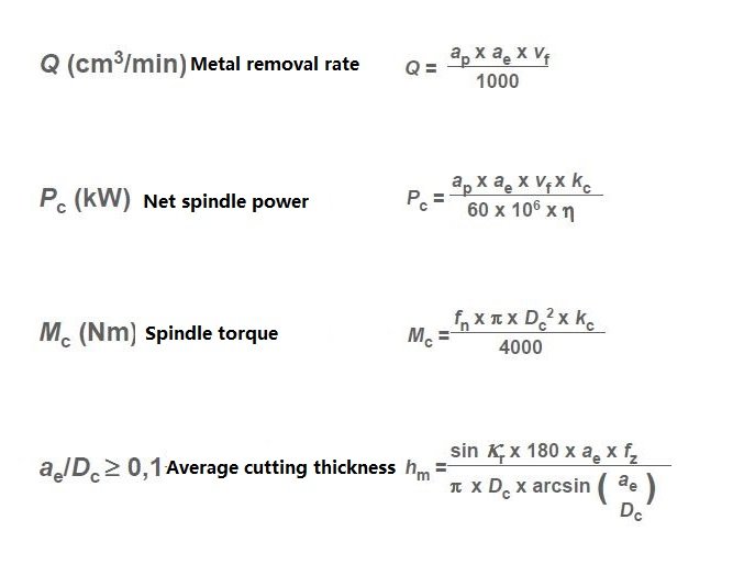
CNC Milling Parameters and Calculation Formulas
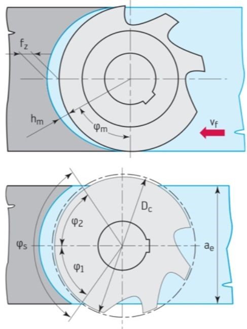
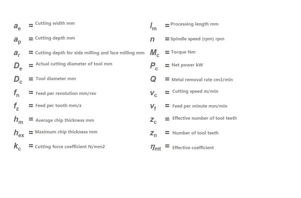
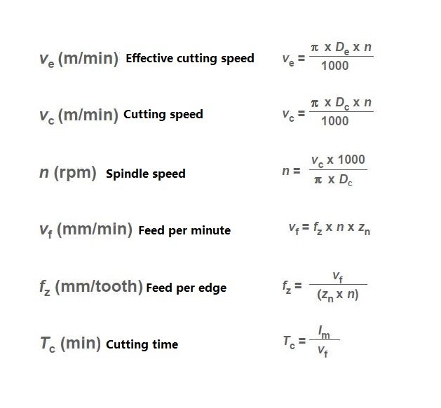
Cutting parameter calculation formula:

CNC Milling Summary
1) Check the power and rigidity of the machine tool to ensure that the diameter of the milling cutter used can be as short as possible when the machine tool uses the tool overhang.
2) The number of teeth of the milling cutter is moderate to ensure that there are not too many blades engaging with the workpiece at the same time during processing to cause vibration. When milling narrow workpieces or cavities, there must be enough blades and workpieces engaged.
3) Appropriate feed per tooth to obtain good cutting results when the chips are thick enough to reduce tool wear. Use positive rake groove inserts to obtain smooth cutting results and minimum power.
4) The milling cutter diameter is suitable for the width of the workpiece.
5) The correct main deflection angle (45 degrees is suitable for general milling).
6) Proper milling cutter position.
7) Use cutting fluid only when necessary; dry milling usually has a better tool life.