Table of Contents
1. What is a Flange
Flanges, also known as flange discs or flanges, are components used to connect shafts to each other. They are employed for connecting pipe ends. Flanges are also used on equipment inlets and outlets to connect two pieces of equipment, such as gear reducer flanges.
Connections between vessel components can be either permanent (welded) or removable. Due to production process requirements and for ease of manufacturing, transportation, installation, and maintenance, removable flange connections are commonly used between vessel sections, between vessel sections and heads, between pipes, and between pipes and valves.
Although detachable structures include flange connections, threaded connections, and socket-weld connections, flange connections are most widely used in chemical and pharmaceutical equipment and piping due to their unique advantages of reliable sealing, high strength, and broad applicability.
2. Structure and Sealing Mechanism of Flange Connections
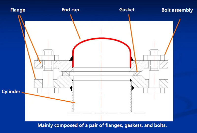
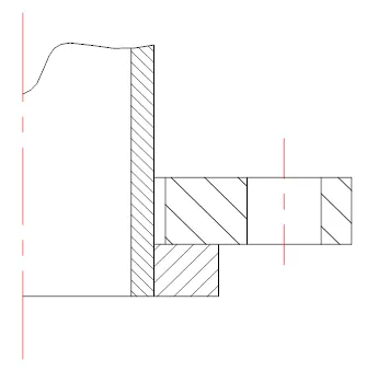
Working Principle: Bolt pre-tensioning compresses the gasket between flange sealing surfaces, solidifying it and filling irregular gaps on the sealing surfaces. This prevents permeation leakage through capillary pores within the gasket and interfacial leakage between the gasket and sealing surfaces, thereby achieving pre-sealing.
The conditions for ensuring leak-free flange connections are: During pre-tightening, the pre-tightening pressure applied to the gasket must not be lower than the pre-tightening sealing pressure. During operation, the residual pressure applied to the gasket must not be lower than the working sealing pressure.
3. Flange Type
Classification based on the degree of integration between flanges and equipment/pipelines:
1. Integral Flanges
Socket Weld Flanges: Used in applications with moderate temperature and pressure (specific values defined in standards).
Butt Weld Flanges: Suitable for high-pressure, high-temperature, and critical environments involving toxic, flammable, or explosive substances. Higher cost.
Differences between Socket Weld and Butt Weld Flanges:
① Different weld forms: Butt welds can undergo radiographic testing, whereas slip-on welds cannot. Slip-on flanges feature two fillet welds, while butt-weld flanges have a single butt weld.
② Different nominal pressures: Necked slip-on flanges have nominal pressures of 0.6–4.0 MPa, while necked butt-weld flanges range from 1–25 MPa. Clearly, necked slip-on flanges are suitable for lower pressure ratings.
③ Different Connection Methods: Slip-on flanges generally connect only to pipes and cannot directly connect to butt-welded fittings. Butt-weld flanges can directly connect to all butt-welded fittings (including elbows, tees, reducers, etc.), as well as pipes.
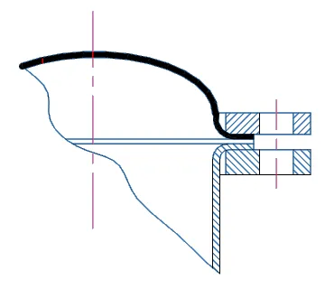
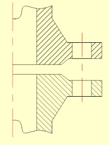
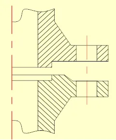
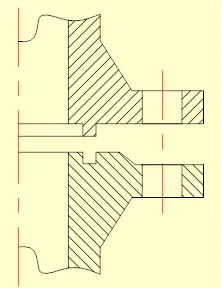
2. Loose Flanges
Characteristics: The flange is not permanently bonded to the pipe or vessel. Suitable for low-pressure applications, it avoids inducing additional bending stresses in non-ferrous metal and stainless steel equipment and pipe shells. When manufactured from carbon steel, it reduces consumption of precious metals. However, loose flanges exhibit poor rigidity.
Connection methods between flanges and vessels or pipes are as follows:

3. Threaded Flanges
Widely used in small-diameter high-pressure pipelines, these flanges impose minimal additional stress on the pipe wall.
4. Flange Shape
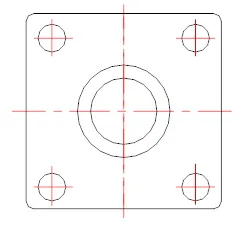
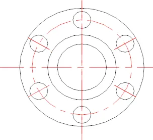
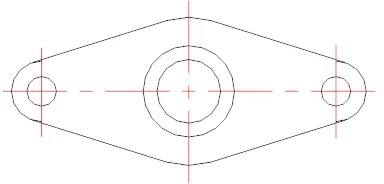
Generally speaking, flanges come in disc or flanged disc shapes, with some being square or oval (waisted).
5. Factors Affecting Flange Sealing
The primary factors affecting flange sealing include: bolt preload, sealing surface configuration, gasket properties, flange stiffness, and operating conditions.
Sealing Surface Configuration:
Flat Type: Features a simple structure and easy machining, facilitating corrosion protection or lining. However, gaskets are prone to extrusion and difficult to compress tightly. Suitable for low-pressure, small-size, non-toxic applications with less stringent sealing requirements.
Concave-Convex Type: Offers good alignment and superior sealing performance, suitable for medium-pressure applications with elevated temperatures.
Tongue-and-groove type: Offers excellent alignment, reliable sealing, narrow gasket width, and low clamping force requirements. Suitable for flammable, explosive, toxic, and high-pressure applications. However, machining and maintenance present challenges.
The selection principle for the clamping surface is: ensure reliable sealing while striving for ease of machining, convenience in assembly, and low cost.
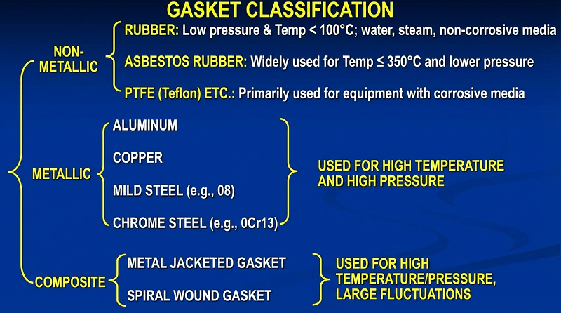
6. Gasket Performance
In flange connections, sealing effectiveness largely depends on the sealing performance of the gasket.
1. Material Requirements: Corrosion-resistant, non-contaminating to products, possessing adequate elasticity, appropriate mechanical strength and flexibility, and resistant to deterioration, hardening, or softening under temperature changes.
2. Classification:
7. Standards for Pressure Vessel Flanges and Pipe Flanges
Vessel flanges are exclusively used for connecting vessel shells, such as between shell sections or between a shell section and a head. Pipe flanges are solely used for connecting pipes.
Special Note: The two types are not interchangeable.
Vessel Flanges:
JB/T4700~4707 “Pressure Vessel Flanges”
Pipe Flanges:
HG20592~20635 “Steel Pipe Flanges, Gaskets, and Fasteners”
GB/T9112~9125 “Steel Pipe Flanges”
JB/T74~90 “Steel Pipe Flanges, Gaskets, and Fasteners”
8. Three Key Parameters in Flange Standards
1. Nominal Diameter DN:
The nominal diameter of a flange refers to the nominal diameter of the vessel or pipe with which the flange mates. For vessels, the nominal diameter denotes the vessel’s inner diameter (except for vessels with a tubular shell made of pipe). For pipes, the nominal diameter indicates its nominal size, which is a value between the pipe’s inner and outer diameters, typically close to the pipe’s inner diameter. Steel pipes with the same nominal diameter have identical outer diameters. Since wall thickness varies, their inner diameters also differ.
2. Nominal Pressure PN:
Nominal pressure represents pressure ratings established for standardization purposes.
3. Maximum Allowable Working Pressure:
The nominal pressure specified in pressure vessel flange standards is determined based on flange material 16Mn (or 16MnR) and a design temperature of 200°C. When flange material or temperature conditions change, the maximum allowable working pressure of the flange will increase or decrease accordingly.