Threads, as one of the most common connection methods in mechanical components, are widely used in machinery, automotive, electronics, and piping systems. Proper thread design not only determines the reliability of part assembly but also affects the overall structural strength and durability. Thread manufacturing encompasses various processes such as cutting, rolling, extrusion, casting, and welding, while also requiring compliance with standardized specifications like ISO metric threads and Unified National (UN) threads.
This guide systematically introduces the fundamentals of threads, standard systems, machining methods, and key design considerations in CNC machining, aiming to help engineers and manufacturers achieve efficient and high-precision thread production.
Table of Contents
The Basic Concept and Composition of Thread
What Are Threads Made Of?
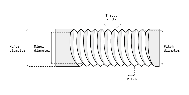
Threads can be internal (female) or external (male), and are usually designed to fit together. On technical drawings, threads can be displayed (or specified) by defining the following parameters.
Thread Parameters
Thread Series: Refers to the thread profile or form, such as UN (Unified National) or Metric.
Thread Type: Within each series, there are different subtypes — for example, UNC (Unified National Coarse) and UNF (Unified National Fine) for UN threads, or M and MJ for metric threads.
Nominal Diameter / Major Diameter / Thread Size: Indicates the overall size of the thread, referring to its major (outer) diameter.
Minor Diameter: Should generally be approximately the same as the drill (hole) size.
Pitch: The linear distance a point on the thread travels parallel to the axis during one complete revolution.
Depth: The depth to which the thread extends into a hole.
Tolerance: The allowable deviation in thread fit or dimension.
Class of Fit / Tolerance Class: Defines the range of permissible variations for thread dimensions, including major, minor, and pitch diameters for both internal and external threads.
Drill Size: Specifies the drill diameter required before tapping. This definition is commonly found in many thread size charts, and its value essentially corresponds to the minor diameter.
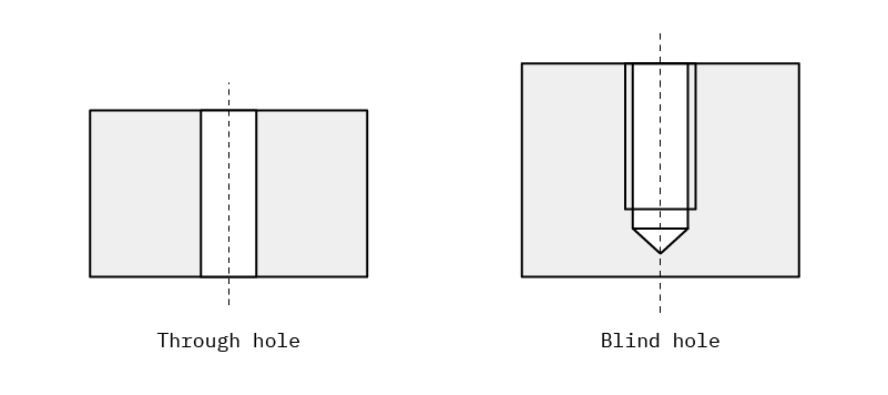
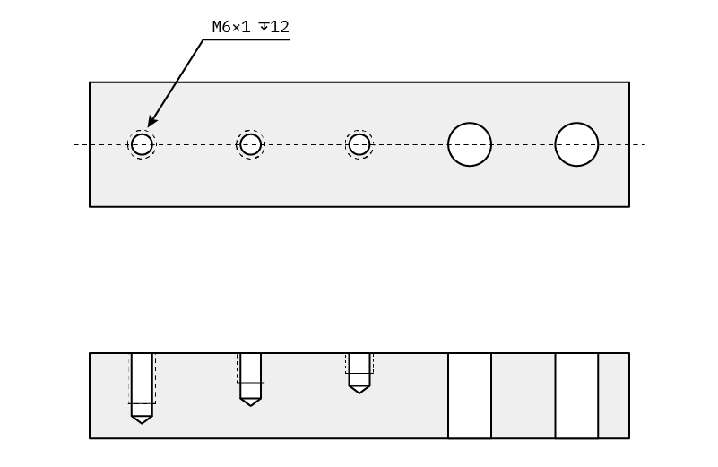
Blind Holes and Through Holes
There are two types of holes in which threads can be defined: blind holes and through holes.
- Through Hole:
A hole that goes entirely through a surface. Its depth corresponds to the thickness of the material or wall it passes through. - Blind Hole:
A hole that does not go completely through the surface. Its depth must be specified separately.
Overview of Thread Types
There are various types of threads available, with metric and unified threads being the most common.
Metric Threads (M)
Metric threads follow the ISO metric international standard and are among the most widely used thread types.
Unified Threads (UNC / UNF / UN / UNEF)
These are imperial (inch-based) standards, typically consisting of coarse (UNC) and fine (UNF) thread series. The UN designation refers to a set of standardized thread series with a uniform number of threads per inch.
Pipe Threads (NPT / NPS / NPTF)
Commonly used for threaded pipe fittings, these threads are designed to ensure a secure, leak-resistant connection.
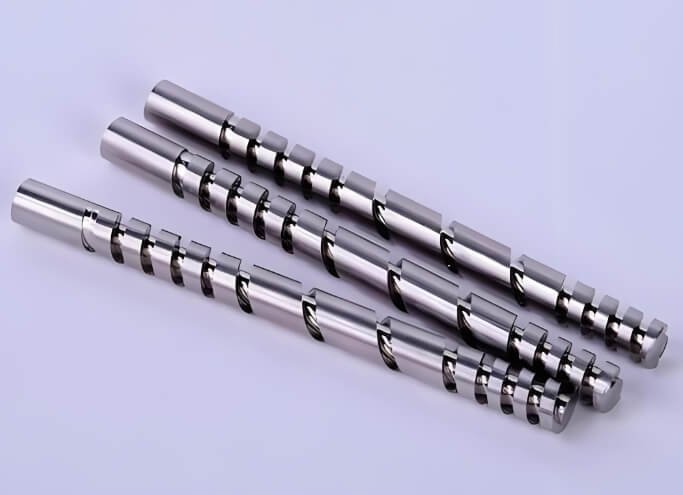
Multi-Start Threads
These consist of two or more intertwined thread starts running parallel to each other, allowing for faster linear motion per rotation.
British Standard Pipe Threads (BSPT)
Typically used for threaded pipe fittings, similar in application to NPT threads but based on British standards.
Thorlabs Threads
A brand-specific thread specification used for creating adapters compatible with Thorlabs optical equipment.
Trapezoidal Threads
A form of power transmission thread, characterized by a trapezoidal profile for higher load-bearing capability and smooth motion.
Metric Threads in Detail
As a standard, metric threads can be defined simply by specifying their type and size (e.g., M10).
The size corresponds to the nominal (major) diameter of the thread, while the pitch and depth follow general ISO metric standards (see reference tables).
Unless otherwise specified, all metric threads are assumed to be through holes.
For blind holes, the thread depth must always be explicitly indicated.
Thread Tolerance Class – Metric Threads
The tolerance class defines the thread tolerance, sometimes referred to as the thread fit.
- Internal threads use uppercase letters (e.g., 6H).
- External threads use lowercase letters (e.g., 6g).
By default, internal threads use 6H, and external threads use 6g, unless another tolerance is specified on the technical drawing. These defaults are based on common industry practice.
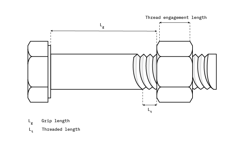
According to ISO 965-1, the tolerance class is determined by the length of thread engagement, which is important for defining the component engagement length—a key factor in load-bearing calculations.
Tolerance Position and Types
The tolerance position determines which type of tolerance is used. The main ones are g and h.
- G (internal) or g (external) tolerance defines a tolerance that varies with the pitch diameter.
- H (internal) or h (external) tolerance defines a static tolerance that does not vary with the pitch diameter.
Sometimes, you’ll see a combined callout that specifies both internal and external threads, indicating a fit class. For example:
6H/6g
| Recommended tolerance grades for internal threads | ||||||
| Tolerance position G | Tolerance position H | |||||
| Thread accuracy | S | N | L | S | N | L |
| High | – | – | – | 4H | 5H | 6H |
| Medium | (5G) | 6G | (7G) | 5H | 6H | 7H |
| Low | – | (7G) | (8G) | – | 7H | 8H |
| Recommended tolerance grades for external threads | ||||
| Thread accuracy | High | Medium | Low | |
| Tolerance position e | S | – | – | – |
| N | – | 6e | (8e) | |
| L | – | (7e6e) | (9e8e) | |
| Tolerance position f | S | – | – | – |
| N | – | 6f | – | |
| L | – | – | – | |
| Tolerance position g | S | – | (5g6g) | – |
| N | (4g) | 6g | 8g | |
| L | (5g4g) | (7g6g) | (9g8g) | |
| Tolerance position h | S | (3h4h) | (5h6h) | – |
| N | 4h | 6h | – | |
| L | (5h6h) | (7h6h) | – | |
Examples of Metric Threads in Practice
- Standard ISO thread:
M10 x 1.5-6H LH - Standard ISO thread:
M10
Why Are These Callouts So Different?
For metric threads, you can use a simplified designation—as in the second example—by simply indicating the thread series (M) and size (10).
In this case, all other parameters default to standard values.
However, for blind holes, you must always specify the thread depth, since there is no standard default depth (see reference table).
| Thread Series | Thread Size (Nominal Diameter) | Pitch | Fit Class | Depth | Rotation Direction |
|---|---|---|---|---|---|
| M | 10 | 1.5 | 6H | Through | Left-hand thread |
| M | 10 | Not specified, default standard pitch for this thread size | Not defined, default 6H | Not specified, default assumed as through for through holes. Incomplete indication for blind holes | Not specified, default right-hand (RH) |
Unified Threads
Remember, the fit class defines the tolerance range of thread dimensions, and it is always associated with whether the thread is external (B) or internal (A). There are six types of fits applicable to unified threads:
- 1A and 1B — The loosest tolerances, very rare. Typically used when quick assembly/disassembly is required.
- 2A and 2B — “Medium” tolerances, the most common fit. This is the best balance between thread performance and convenience.
- 3A and 3B — Very tight tolerances. Used when thread integrity is critical for the safety of the final product.
If no fit is specified, the default fit class for internal threads is 2A, and for external threads is 2B.
Thread Design Tips
1. Stay Standardized
In manufacturing, one of the biggest time- and cost-saving strategies is to maintain standardization. Experienced engineers learn through trial and error the importance of keeping components as universal as possible—even when designing custom products. If there is an existing solution, don’t overcomplicate it. This applies to threads as well: always choose commonly used series and sizes whenever possible.
- Standard series: UN (UNC and UNF) and Metric (M)
- Common sizes: UN list, Metric list
2. Pay Attention to Hole Sizes
One of the most common mistakes when manufacturing threaded parts is a mismatch between the thread size and the hole size. This can cause confusion over whether the thread or the hole diameter is correct. As a manufacturer, assumptions cannot be made, and such confusion can delay production by at least 1–2 days.
3. Specify Blind Hole Thread Depth
Incomplete thread specifications are another cause of delays. A blind hole is a hole that does not go through the entire thickness of the part. If a line is drawn on a blind hole, the depth must be clearly indicated.
Main Methods of Thread Manufacturing
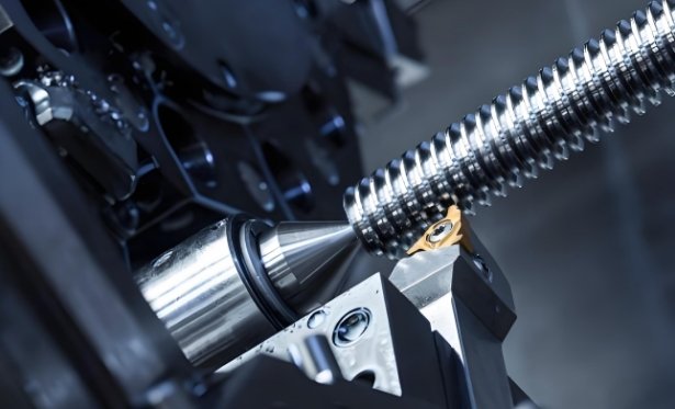
1. Thread Cutting
Equipment: Thread lathe, thread milling machine
Thread cutting removes material mechanically from a workpiece to form threads. This method is suitable for various materials and thread sizes.
Processes:
- Turning: Using a thread lathe with single- or multi-point thread cutting tools.
- Milling: Using a thread milling machine with a rotating cutter.
Features:
- High precision and good surface quality.
- Suitable for both internal and external threads.
- Removes a large amount of material, suitable for harder materials.
2. Thread Rolling
Equipment: Thread rolling machine
Thread rolling is a non-cutting method that forms threads through plastic deformation.
Process:
- Place the workpiece in a die on the rolling machine, and rotate/apply pressure to plastically deform the material.
Features:
- Increased material strength with no cutting loss.
- Improved surface hardness and wear resistance.
- Suitable for high-strength materials and precision threads.
3. Thread Extrusion
Equipment: Extrusion machine
Thread extrusion is similar to thread rolling but involves higher pressure and more pronounced material flow.
Process:
- Apply high pressure via an extrusion machine to shape the material in the die into threads.
Features:
- Fast processing and high production efficiency.
- Suitable for internal and external threads on pipes and rods.
4. Thread Casting
Equipment: Casting equipment
Thread casting forms threads directly during the casting process.
Process:
- Design the thread shape in the mold; the material fills the mold to form the thread during casting.
Features:
- Suitable for mass production.
- Saves material and machining time.
- Accuracy and surface quality are relatively lower.
5. Thread Welding
Equipment: Welding equipment
Thread welding forms threads on a workpiece surface through welding.
Process:
- Use welding equipment to build up the thread shape on the workpiece surface.
Features:
- Suitable for repairing worn threads or threading materials difficult to cut.
- Strength and durability are lower than cutting or rolling threads.
6. Thread Grinding
Equipment: Thread grinder
Thread grinding uses grinding wheels or tools to precisely finish threads.
Process:
- Process threads on a thread grinder by accurately controlling the relative motion between the tool and the workpiece.
Features:
- Extremely high precision and good surface finish.
- Suitable for high-precision threads and complex thread shapes.
7. Thread Stamping
Equipment: Punch press
Thread stamping forms threads on sheet metal using a punch press.
Process:
- Gradually form threads by pressing the sheet metal with a die on the punch press.
Features:
- High production efficiency, suitable for mass production.
- Suitable for threading thin sheet materials.
Common Methods of Thread Processing
1. Tapping
Tapping is a common thread processing method, mainly performed by cutting threads on the hole wall using a tap. Tools such as taps and drill bits are required. First, a hole of the appropriate size is drilled in the workpiece, then the tap is inserted into the hole. By rotating either the tap or the workpiece, threads are cut. Tapping offers high precision and efficiency and is suitable for processing threads of various materials and specifications.
2. Thread Turning
Thread turning is mainly performed on a lathe and is a highly efficient and precise method for cutting threads. Before turning, the cutting tool and workpiece must be installed, and the lathe parameters properly adjusted. Threads are then cut by rotating either the tool or the workpiece. Thread turning can produce threads of different sizes and materials with high precision and efficiency.
3. Helical Milling
Helical milling is a more specialized thread processing method that cuts threads through the relative motion of a rotating milling cutter and the workpiece. Its advantages include high precision and faster cutting speed, making it suitable for large-scale production. However, helical milling requires specialized cutters and fixtures, which increases costs.
4. Thread Rolling
Thread rolling is a relatively modern thread processing method, forming threads by pressing the workpiece surface with rolling dies. The advantages of thread rolling include high precision, lower surface roughness, and improved fastening strength and wear resistance. However, it requires specialized rolling dies and fixtures, making it more expensive.
Considerations for Thread Processing in CNC Machining
External Threads and Internal Threads
A simple way to remember the difference is: external threads are found on screws and bolts, located on the outside of the hardware. Internal threads are inside the main component and receive and lock the threads of screws and bolts. More detailed information about external and internal threads can be found later in this design tips section.
Bolt Pitch
When discussing threads on bolts and screws, it’s not a one-size-fits-all scenario. In addition to metric threads, there are three main types of imperial threads, which are part of the Unified Thread series:
- UNC (coarse pitch): 20 threads per inch (tpi)
- UNF (fine pitch): 28 tpi
- UNEF (extra fine pitch): 32 tpi
Note that adding a UNEF pitch requires our precision machining services, accessible through our quoting system. For example, if you want to use a #4-40 screw, you know that the #4 screw has a thread diameter of 0.11 inches (2.794 mm) and 40 threads per inch, meaning a very fine pitch.
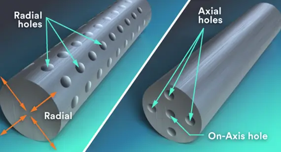
Holes for Turned Parts
For turned parts, there are three types of holes that can accommodate internal threads:
- Through Axial Holes: Holes that go directly through the center of the turned part from one end.
- Axial Blind Holes: Holes that start from one end but do not pass completely through the center.
- Radial Holes: Holes that pass through the outer curve of the turned part.
Internal Threads
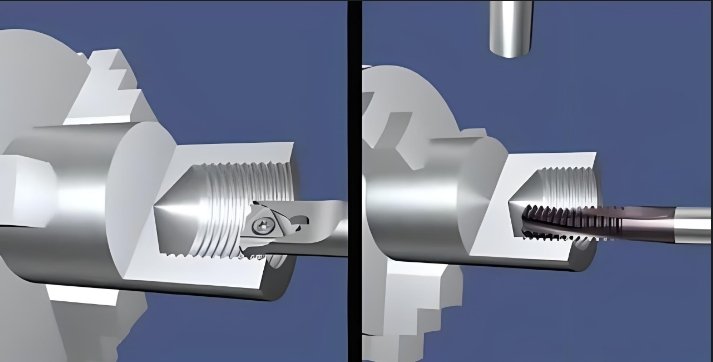
Internal threads are machined using single-point thread tools rather than traditional taps. When machining an internal threaded hole, the hole may be longer than the reach of our threading tool. In this case, you have several options:
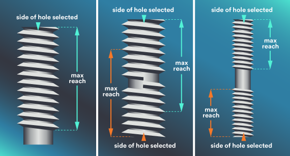
- For long through-holes exceeding the tool’s maximum range, start from the side where the screw is expected to engage (see image 1 in the panel above). If the screw needs to go completely through the part, you must also use a tap to finish it (second step).
- You may choose both sides of the feature to create threads (see image 2), but pay attention to the maximum thread depth to avoid overlap inside the hole. This raises concerns for double-sided threading because of the risk of crossed threads and incomplete screw engagement. Usually, threading from both sides is fine as long as the threads do not intersect (see image 3).
An important consideration involves the different diameters in creating threads. You must consider three measurements: major (wide) thread diameter, minor (narrow) thread diameter, and the pilot hole diameter, into which the thread feature will be machined.
If your design instructs the manufacturer to mill a pilot hole matching the major (wide) thread diameter, the hardware you use will never fit correctly—it may spin endlessly inside the hole. The only solution at that point would be using larger hardware, which may be functionally unacceptable or inconsistent with your design. Ensure any pilot holes reflect the minor thread diameter to avoid such issues.
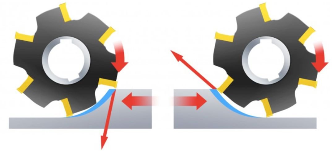
External Threads
The advantage of external threads on turned parts is that the thread can extend the length of the part as long as turning conditions are met. External thread milling is performed in two stages. The first set of threads is milled along half of the part, then the other side is milled, intersecting along the part’s centerline. This process is suitable for 1/2-inch threads, but we recommend trimming threads to remove excess material or mismatched areas.
Smaller external threads (like #6-32) are harder to mill with ball or flat-end cutters because the pitch is too tight, leaving a large radius at the thread root. Thread cutting dies may be required to remove remaining material. On many parts, a radius of 0.008 to 0.016 inches (0.2032 to 0.4064 mm) will remain.
External threads on turned parts are greatly improved because the part rotates on its axis, and sharp single-point thread tools can produce high-quality threads. The design of external threads is similar to internal holes. Remember, threads must be removed so our software can digitally see the external diameter to determine the required thread type.
Alternatives to Threading
For most metal parts, threading is a good way to achieve strong connections between components. However, sometimes it’s not enough, especially for parts made from weaker materials like plastic or aluminum. That’s where inserts come in.
For example, with plastic parts, it’s important to remember that threads will inevitably wear out much faster than those on metal parts. The solution? Consider adding special coil inserts into the plastic components to ensure longer part life. These robust small inserts provide strong threads even in weaker materials. Essentially, you design a hole at the desired location, and later the insert can be added to the part.
There is considerable flexibility because coil inserts are available in both UNC and UNF threads, ranging from #2 to 1/2 inch, and in metric threads from M2 to M12.
Conclusion
Threads are one of the most common connection methods in mechanical components, and their design and machining directly determine the assembly accuracy, structural strength, and durability of parts. From basic thread parameters and standard systems to cutting, rolling, extrusion, casting, welding, and CNC machining methods, every step is crucial. Whether for metal parts or softer materials like plastic and aluminum, proper thread design, hole size matching, and blind hole depth specification are key to ensuring efficient machining and long-term performance.
At YPMFG CNC Machining, we combine extensive thread machining experience with advanced CNC technology to provide high-precision, reliable thread machining solutions for our clients. Whether for standard components or complex custom parts, ypmfg CNC Machining ensures the quality and assembly performance of every thread, providing solid support for your mechanical products.