What is a Gear?
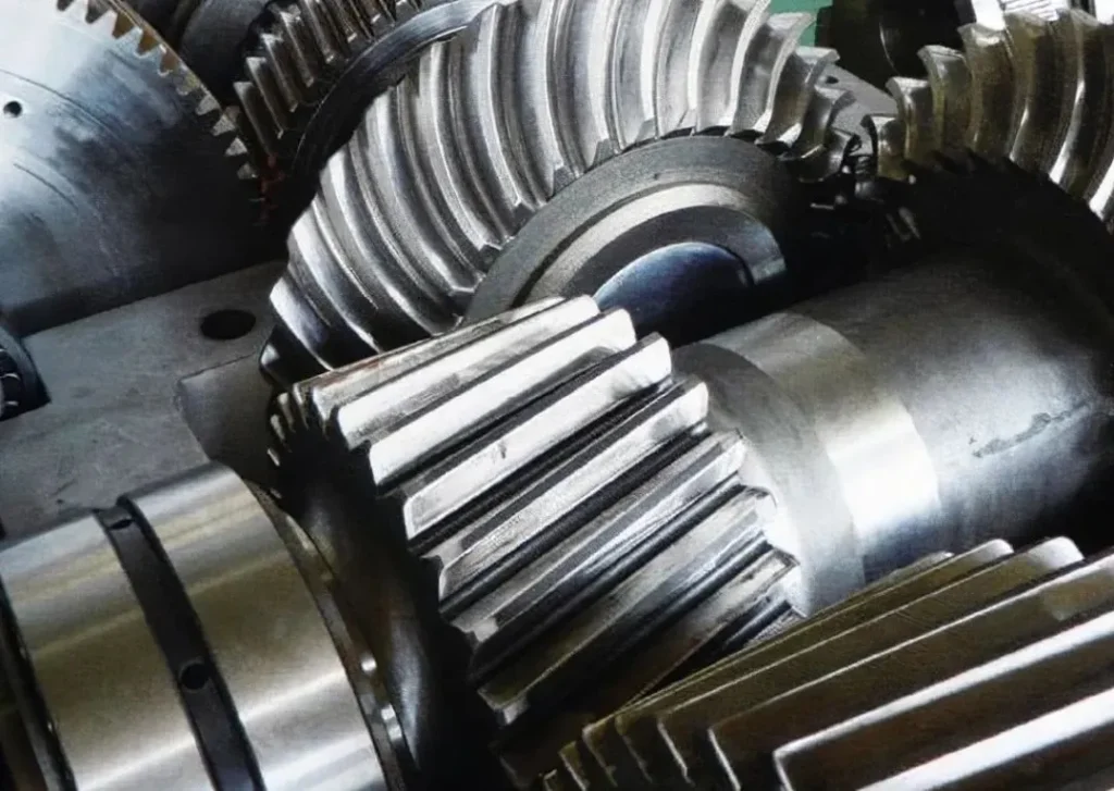
Gears are wheel-shaped mechanical parts that transmit torque by meshing teeth. Gears can achieve functions such as changing speed and torque, changing movement direction and changing movement form by transmitting with other tooth-shaped mechanical parts (such as another gear, rack, or worm). Gear mechanisms are widely used in industrial products due to their advantages, such as high transmission efficiency, accurate transmission ratio and wide power range. The teeth between two gears intersect and mesh with each other, and the teeth of one gear will drive the teeth of the other gear to rotate to transmit power. The two gears can also be separated to apply power.
Table of Contents
Composition and Name of Gears
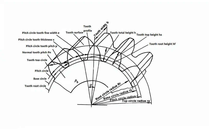
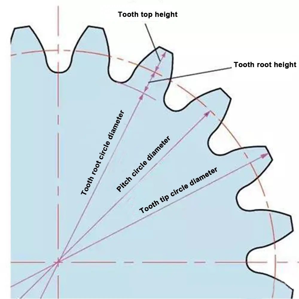
Addendum circle: The circle passing through the top of all gear teeth is called the addendum circle. Its radius is represented by ra, and its diameter is represented by da.
Root circle: The circle passing through the bottom edge of all tooth grooves is called the root circle. Its radius is represented by rf, and its diameter is represented by df.
Pitch circle: In order to facilitate the calculation of the dimensions of each part of the gear, a circle is selected on the gear as the basis for calculation, and this circle becomes the pitch circle. The radius is represented by r, and the diameter is represented by d. All parameters on the pitch circle do not have a superscript.
Tooth top height: The part of the gear tooth between the pitch circle and the tooth top circle is called the tooth top, and its radial height is called the tooth top height. It is represented by ha.
Root height: The part of the gear tooth between the pitch circle and the tooth root circle is called the tooth root, and its radial height is called the tooth root height. Hf represents it.
Tooth full height: The radial height of the gear tooth between the tooth top circle and the tooth root circle is called the tooth full height, represented by h.
Tooth thickness: On any circumference, the arc length between the tooth profiles on both sides of the gear tooth is called the tooth thickness on the circumference, represented by SK.
Tooth groove width: The space between two adjacent teeth of the gear is called the tooth groove. On any circumference, the arc length of the tooth groove is called the tooth groove width on the circumference, represented by ek.
Tooth pitch: On any circumference, the arc length of the same side of two adjacent teeth is called the tooth pitch on the circumference, represented by Pk.
On the base circle, the arc length of the same side of two adjacent teeth is called the base circle pitch, represented by Pb.
Normal pitch: The distance between the same side of two adjacent teeth in the normal direction is called the normal pitch, represented by Pn. From the involute property, it can be seen that Pn=Pb°.
Working Principle of Gears
The working principle of gears: It is based on the meshing movement between teeth. When two gears are meshed, one gear is called the driving gear, and the other gear is called the driven gear. The driving gear generates torque (torque) by rotation and transmits the torque to the driven gear, making it rotate together.
Types of transmission: Gear transmission, chain transmission, belt transmission, hydraulic transmission, gas transmission, wireless transmission.
Advantages of gear transmission: Gear transmission has the advantages of high transmission efficiency, high transmission accuracy, and large load-bearing capacity. In addition, gear transmission can also achieve the matching of different speeds and torques, so it is widely used.
Characteristics of Gear Transmission
Advantages
1. High transmission efficiency: The transmission efficiency of gear transmission is usually higher than other transmission methods, reaching more than 95%.
2. High precision: The gear manufacturing process has high precision, and the gear meshing precision is high, which can ensure the stability and accuracy of the transmission.
3. Strong load-bearing capacity: Gear transmission can withstand large torque and load and is suitable for occasions requiring high-power transmission.
4. Compact structure: The gear transmission structure is complex and requires more materials to support and withstand torque and load, so it is relatively heavy.
5. Reliable operation and long service life: Gear transmission works reliably and has a long service life.
6. Wide range of application: The power range transmitted by gear transmission is extremely wide, ranging from 0.001W to 60000kW, the circumferential speed can be very low or as high as 150m/s, which is difficult to match with belt transmission and chain transmission.
7. It can realize the transmission between any two axes in space, such as parallel axes, intersecting axes, and staggered axes: this is also impossible for belt transmission and chain transmission.
Disadvantages
1. High noise: Gear transmission will generate noise during operation, causing certain interference and impact on the surrounding environment and operators.
2. Difficult to install and adjust: Gear transmission requires high technical requirements for installation and adjustment and needs to consider issues such as the accuracy and clearance of gear meshing.
3. High weight: The gear transmission structure is complex and requires more materials to support and withstand torque and load, so it is relatively heavy
4. Fixed transmission ratio: The transmission ratio of gear transmission is fixed, and the transmission ratio cannot be adjusted at will during operation.
5. High manufacturing and installation precision requirements: Gear transmission has high manufacturing and installation precision requirements, is expensive, and has high vibration and noise when the precision is low.
6. No overload protection: Gear transmission has no overload protection.
In general, gear transmission is suitable for high-power, high-precision, and high-load occasions, but noise and weight issues need to be considered. When choosing a transmission method, its advantages and disadvantages need to be considered comprehensively according to the actual situation.
Gear Classification
1. Spur Gear
This is a cylindrical gear with teeth parallel to the axis and is widely used. Moreover, it is the easiest to manufacture.
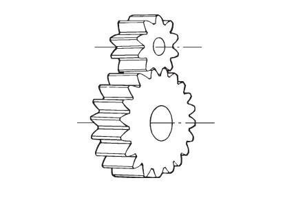
2. Helical Gear
This is a cylindrical gear with helical teeth. Helical gears can handle more loads than spur gears and are quieter. They are widely used in industry. The disadvantage is the axial thrust that the helical shape creates.
3. Double Helical Gear
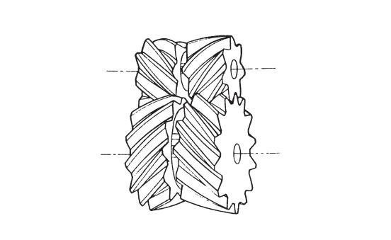
This is a gear with left-hand and right-hand helical teeth. The double helix form balances the inherent thrust.
4. Crossed Helical Gear
If two helical gears with opposite helix angles are meshed on a crossed shaft, they are just conventional helical gears as separate gear components. They provide a simple gearing method to accommodate any angle of inclination of the shaft. Because they are point contacts, their load-carrying capacity is very limited.
5. Internal Gear
This is a cylindrical gear but with teeth located inside the cylinder. It can mesh with spur gears. Internal gears are often used in planetary gear systems.
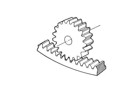
6. Spur Rack
Spur Rack
This is a straight-line shaped gear that can mesh with a spur gear of any number of teeth. A spur rack is a portion of a spur gear that has an infinite radius.
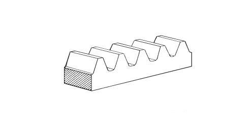
7. Helical Rack
Helical Rack
This is a linear gear meshing with a helical gear. Again, it can be considered as a section of a helical gear with infinite radius.
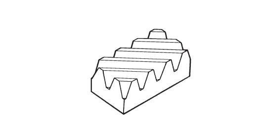
8. Face Gear
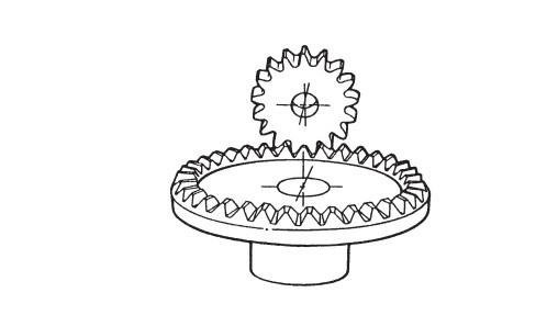
Face Gear
This is a pseudo-bevel gear with a limited shaft angle of 90°. A face gear is a disk with a toothed ring face on the side, hence the name face gear. The tooth surface is tapered towards its center. The gear it is paired with is a normal spur gear. It is usually manufactured on a normal gear-shaping machine.
9. Straight Bevel Gear
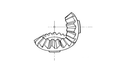
This is a gear with conical teeth and the same baseline (parent line) as the pitch cone. Straight bevel gears are the simplest to produce and the most widely used bevel gear series.
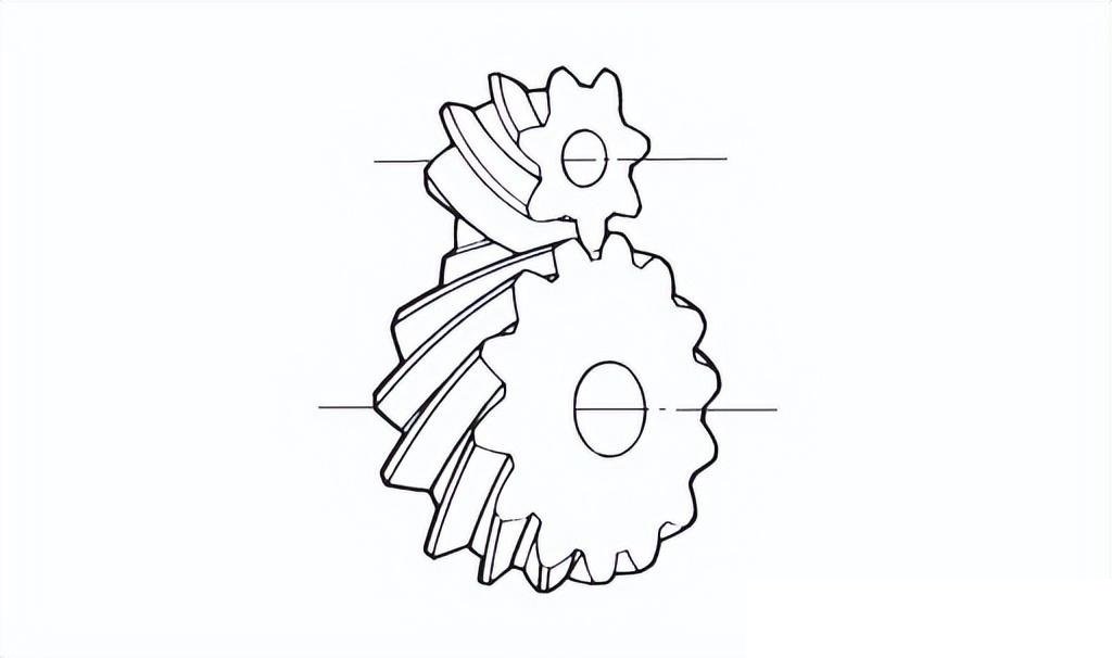
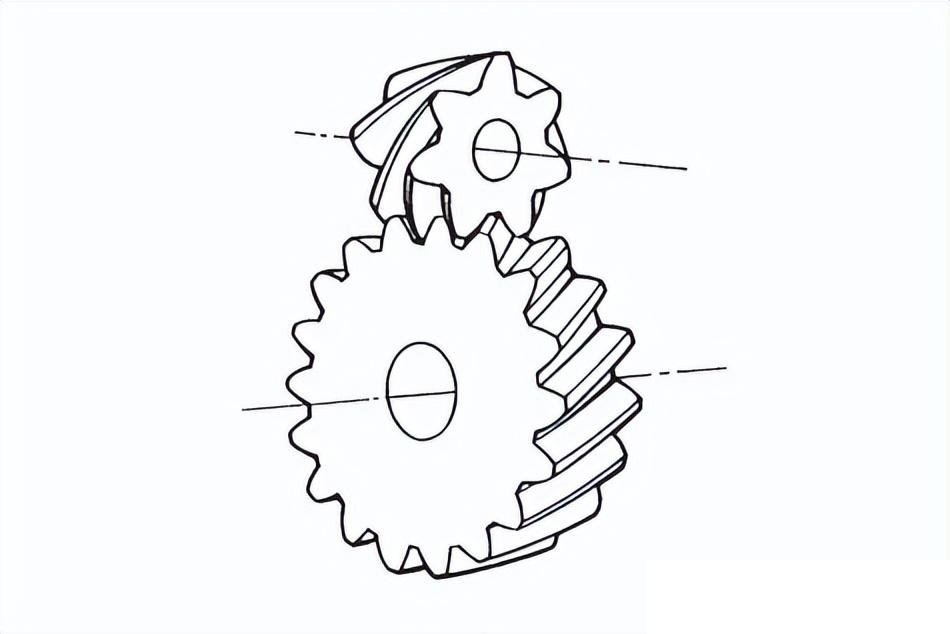
10. Spiral Bevel Gear
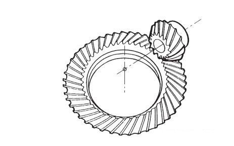
This is a bevel gear with helical teeth at a helix angle. It is much more complex to manufacture but offers greater strength and lower noise.
11. Zerol Gear
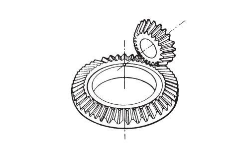
A zero-degree bevel gear is a special case of spiral bevel gear. It is a bevel tooth advancement with a helix angle of zero. It has the characteristics of spur bevel gear and spiral bevel gear. The forces acting on the teeth are the same as those of spur bevel gear.
12. Hypoid Gear
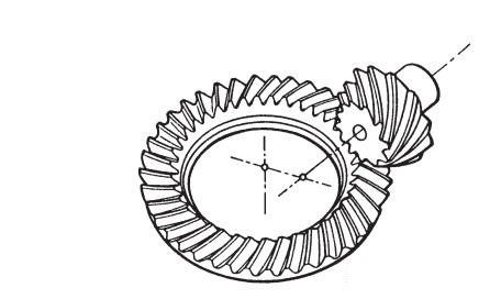
This is a deviation from the bevel gear, and its origin is a special development of the automotive industry. It can increase the diameter of the small wheel, making it easy to achieve double-span support. By using the small wheel under-bias, the center of gravity can be lowered to make the car more comfortable. By using the small wheel upper bias, the off-road vehicle can have stronger obstacle-crossing ability. It looks very much like a spiral bevel gear. However, it is complex in design and the most difficult to produce on a bevel gear generator.
13. Worm And Worm Gear
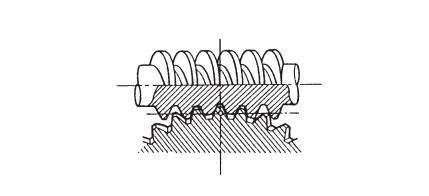
The worm gear pair is the name of the meshing worm and worm wheel. Worm gear transmission is used to transmit motion and torque between interlaced axes in space. The outstanding feature is that the worm provides a very large transmission ratio in a single meshing. The rotation is smooth, and the vibration, impact and noise are very small. However, due to the large meshing friction loss between the tooth surfaces, the transmission efficiency is lower than that of the gear transmission, and it is easy to generate heat and excessive temperature rise.
14. Double Enveloping Worm Gear
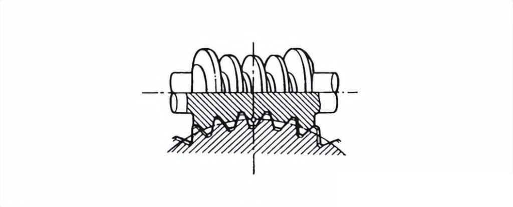
The worm gear set uses a special worm shape, and its indexing surface is a torus. Its load capacity is much higher than that of a standard worm. However, the design, production and testing of this worm gear are very complicated, and few manufacturers can produce it.
Gear Materials and Heat Treatment
When selecting gear materials and their heat treatment, the main considerations are the gear transmission mode, load properties and size, transmission speed and precision requirements, and other working conditions. At the same time, the steel hardenability and tooth surface hardening requirements based on the gear module and cross-sectional size, as well as the matching of gear pair materials and hardness values, should also be considered.
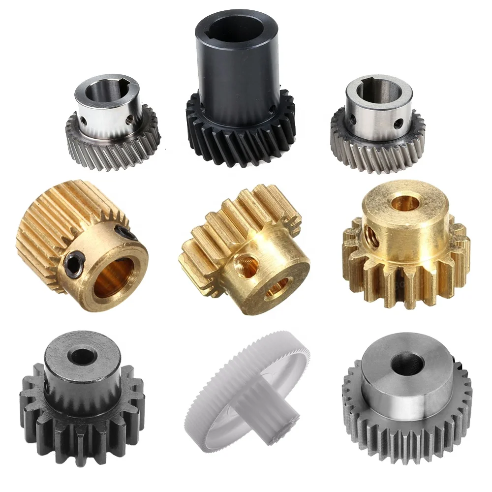
Gears are made of a variety of materials, such as various cast irons, steels, powder metallurgy materials, non-ferrous alloys (such as copper alloys) and non-metallic materials. Steel is the most widely used material, including various low-carbon steels, medium-carbon steels, high-carbon steels and alloy steels.
Appropriate heat treatment of steel gears (such as normalizing and annealing, overall quenching and tempering, quenching and tempering, carburizing, nitriding, surface quenching, etc.) is intended to improve the performance of steel and give full play to the material’s capabilities. It can also improve the cutting performance of steel, improve the quality of gear processing, and extend the service life of gears.
The characteristics and applicable conditions of various steel materials and heat treatment for gears are as follows:
1. Quenched and tempered steel
Steel grades: 45, 35SiMn, 42SiMn, 37SiMn2MoV, 40MnB, 45MnB, 40Cr, 45Cr, 35CrMo, 42CrMo, etc.
Process 1. Quenched and tempered or normalized
1) After quenched and tempered, it has good strength and toughness and is often used in the range of 220~300HBW.
2) When the hardness of the quenched and tempered pinion cannot be increased due to the limitation of the tool, in order to maintain the hardness difference between the large and small gears, the large gear treated with normalizing can be used, but the strength is worse than the quenched and tempered one.
3) The fine cutting of the tooth surface can be carried out after heat treatment to eliminate heat treatment distortion and maintain gear accuracy.
4) No special heat treatment equipment and tooth surface finishing equipment are required, and the manufacturing cost is low.
5) The tooth surface hardness is low and easy to run in, but the bearing capacity of the material cannot be fully utilized.
Applicable conditions: widely used in general medium and low-speed gears with low requirements for strength and precision, as well as large gears with difficult heat treatment and tooth surface finishing.
Process 2. Surface quenching (induction quenching, flame quenching)
1) The tooth surface has high hardness and strong resistance to pitting and wear, the core has good toughness, and residual stress is generated after hardening on the surface, which greatly improves the root strength, the usual tooth surface hardness range is: alloy steel 45 55HRC, carbon steel 4050HRC.
2) In order to further improve the strength of the core, tempering treatment is often performed before surface quenching.
3) The induction quenching time is short.
4) The depth and hardness of the surface hardened layer vary along the tooth surface.
5) Due to rapid heating and cooling, it is easy to crack.
Applicable conditions: widely used in gears with high load-bearing capacity and small size.
2. Carburizing steel
Steel grades: 20Cr, 20CrMnTi, 20CrMnMo, 20CrMo, 22CrMo, 20CrNiMo, 18Cr2Ni4W, 20Cr2Ni4A, etc.
Process: carburizing and quenching
1) The tooth surface hardness is very high, with strong resistance to pitting and wear, the core has good toughness, and the residual stress generated after the surface is hardened greatly improves the tooth root strength, the general tooth surface hardness range is 56~63HRC.
2) Good cutting performance.
3) The heat treatment distortion is large, and the teeth should be ground after heat treatment, which increases the processing time and cost but can obtain high precision.
Applicable conditions: widely used in medium and small gears that require high load-bearing capacity, good impact resistance, high precision and small size.
3. Nitriding steel
Steel grades: 38CrMoAlA, 30CrMoSiA, 25Cr2MoV, etc.
Process: Nitriding treatment
1) It can obtain very high tooth surface hardness, with strong resistance to pitting and wear, the core has good toughness. In order to improve the strength of the core, medium carbon steel is often tempered first.
2) Due to the low heating temperature, the heat treatment distortion is very small, and no grinding is required after nitriding.
3) The hardened layer is very thin, so the load-bearing capacity is not as good as that of carburized and quenched gears, and it is not suitable for occasions with impact loads.
4) The nitriding treatment cycle is long, and the processing cost is high.
Applicable conditions: It is suitable for gears working under larger and more stable loads and for occasions where there is no tooth surface finishing equipment, but a hard tooth surface is required.
4. Cast steel
Steel grades: ZG310-570, ZG340-640, ZG42SiMn, ZG50SiMn, ZG40Cr1, ZG35CrMnSi, etc.
Process: normalizing or tempering and surface quenching
1) Large gears with complex shapes can be manufactured
2) Its strength is lower than that of the same grade and heat-treated quenched and tempered steel
3) It is easy to produce casting defects
Applicable conditions: Used for large gears that cannot be forged.
5. Cast iron
Steel grades: various gray cast irons, ductile irons, malleable cast irons, etc.
1) Low material cost.
2) Good wear resistance.
3) Large gears with complex shapes can be manufactured.
4) Good casting and cutting processability.
5) Low load capacity.
Applicable conditions: Gray cast iron and malleable cast iron are used for low-speed, light-load, and non-impact gears, ductile iron can be used for gears with large loads and impacts.
Design and Manufacture of Gears
1. Gear design steps
1) Determine the module m
The module determines the size of the gear and the load-bearing capacity of the gear.
There are two methods to determine the module.
①Empirical method
Refer to the module of the previous gear. Applicable to the modification and upgrading of existing products.
②Strength verification method
According to the formula table for gear strength verification.
Fill in the table according to the data required in the table, such as the force of the designed gear part, and calculate the minimum module.
Multiply by the appropriate safety factor and select a similar value from the standard module series.
Standard module series table stipulated by China (GB/T 1357-2008)
Note: When selecting the module, the first series should be used first, followed by the second series, and the modules in brackets should be used as little as possible.
| First series | 1 | 1.25 | 1.5 | 2 | 2.5 | 3 | 4 | 5 | 6 | 8 |
| 10 | 12 | 16 | 20 | 25 | 32 | 40 | 50 | |||
| Second series | 1.125 | 1.375 | 1.75 | 2.25 | 2.75 | 3.5 | 4.5 | 5.5 | (6.5) | |
| 7 | 9 | 11 | 14 | 18 | 22 | 28 | 36 | 45 |
2) Determine the number of teeth z
First, it is clear that the minimum number of teeth without root cutting is 17.
Therefore, the number of teeth of the pinion is generally designed to be 17 + 1 to 3. That is, the number of teeth is 18 to 20.
Usually, gears are usually paired with small gears and large gears. After determining the number of teeth of the small gear, calculate the number of teeth of the large gear according to the transmission ratio you need.
3) Other parameters
After the module and the number of teeth are determined, the other parameters of the gear can basically be calculated by the formula related to the two.
The following table is the formula table of spur gear parameters.
| Spur module gears | ||
| Tooth pitch | p | p=πm=πd/z |
| Tooth number | Z | Z=p/m=rp /d |
| Module | m | r1=p/z=pp/)Z+Z( |
| Pitch circle | d | d=mz=da-2m |
| Tooth top circle | da | da=m(z+2)=d+2m=ρ (z+2)/π |
| Tooth root circle | df | df=d-2.5m=m(z-2.5)=da-2h=da-4.5m |
| Tooth height | h | h=2.25m |
| Tooth top height | ha | ha=m=p/m |
| Tooth root height | hf | hq=1.25m |
| Tooth thickness | S | S= ρ /2= mm/2 |
| Center distance | a | a=(mz1 +mz2) /2=(d1 +d2) /2 |
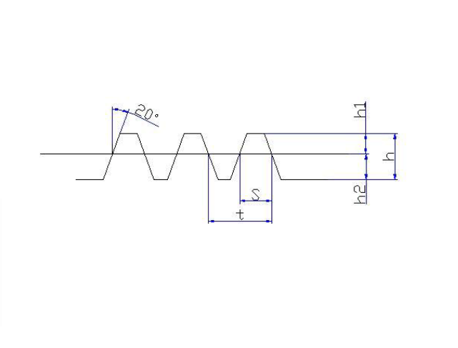
2. Rack parameter design
The rack can be regarded as a gear with a special shape.
The module of the rack is the same as the matching gear.
The formulas for other parameters are shown in the table below
| Rack geometry calculation | ||
| Name | Code | Calculation formula |
| Module | m | |
| Pitch | t | t=Tm |
| Tooth thickness | s | S=1.5708m |
| Radial clearance | C | c=0.25m |
| Tooth top height | h1 | h1=m |
| Tooth root height | h2 | h2=1.25m |
| Tooth working height | hg | hg=2m |
| Tooth full height | h | h=2.25m |
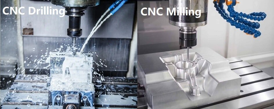
Gear processing process:
Forging – Normalizing – Rough turning of each part, leaving allowance – Finish turning of each part – Hobbing – Chamfering – Inserting keyway – Deburring – Shaving – Heat treatment, Tooth surface quenching – Gear grinding – Honing – Inspection
Want to Learn More Gear Procees? Here!
Gear processing principle
1. Hobbing principle:
Hobbing is the process of processing gears according to the principle of the generating method. It is the process of meshing and rolling of a pair of staggered helical gear pairs. The number of teeth of a helical gear is reduced to 1-4 teeth, and its helix angle is large → worm → slotting, back shoveling → hob The transmission chain connects the hob spindle to the workbench, the tool rotates 1 tooth – the workpiece rotates 1 tooth → conjugate tooth surface, the hob axial feed motion → the motion required to process the full tooth: the generating motion (B11+B12) to form the involute tooth profile and the motion A2 to form the linear tooth length (guide wire)
2.Gear shaping principle:
Gears are cut using a gear-shaped gear-shaping cutter or a rack-shaped comb cutter. When the gear shaping cutter is used for gear cutting, the cutter moves axially back and forth with the main shaft of the gear shaping machine. At the same time, the gear shaping cutter and the workpiece rotate at a certain speed ratio by the machine tool transmission chain to ensure that the workpiece rotates one tooth when the gear shaping cutter rotates one tooth, forming a developing motion, and the gear tooth shape is accurately enveloped.
3.Gear shaping principle:
There are two methods: profiling and developing. Profiling gear shaping uses a template that enlarges the shape of the cut tooth to control the movement trajectory of the single-edged planer to cut the tooth shape. The developing gear shaping method uses a pair of planers to plan the two sides of the gear teeth respectively, and the reciprocating motion trajectory of the planer blade represents the tooth surface of the imaginary crown wheel. The precision of gear shaping can reach 7 to 8 levels, and the processing modulus range is 0.3 to 20 mm. Although the productivity is lower than that of double-disc milling, the tool manufacturing is simple. Gear shaping is widely used in the processing of straight bevel gears.
Calculation of the Main Geometric Dimensions of Gears
1) Names of various parts of the gear

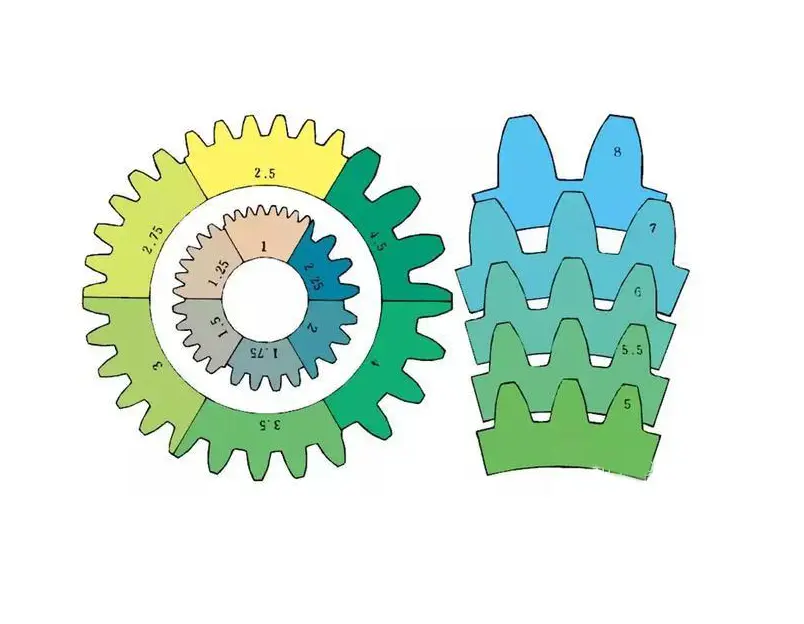
2) The term for the size of gear teeth is module
m1, m3, m8… are called module 1, module 3, module 8. Module is a universal name, using the symbol m (module) and the number (mm>) to indicate the size of the gear teeth. The larger the number, the larger the gear teeth.
In addition, in countries that use imperial units (such as the United States), the symbol (diameter pitch) and the number (the number of gear teeth when the pitch circle diameter is 1 inch) are used to indicate the size of the gear teeth. For example: DP24, DP8, etc. There are also more special names that use the symbol (circumferential pitch) and the number (mm) to indicate the size of the gear teeth, such as CP5, CP10.
The pitch (p) is obtained by multiplying the module by pi. The pitch is the length between two adjacent teeth.
The formula is:
p = pi x module = πm
Comparison of gear tooth sizes with different modules:
3) Pressure angle
The pressure angle is a parameter that determines the gear tooth profile. It is the inclination of the gear tooth surface. The pressure angle (α) is generally 20°. In the past, gears with a pressure angle of 14.5° were very popular.
The pressure angle is the angle between the radius line and the tangent line of the tooth profile at a point on the tooth surface (usually the node). As shown in the figure, α is the pressure angle. Since α’=α, α’ is also the pressure angle.
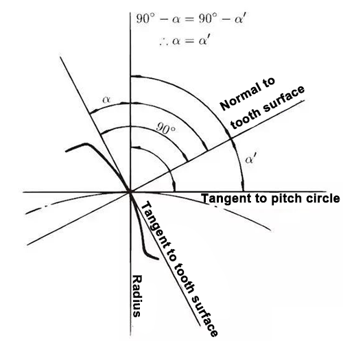
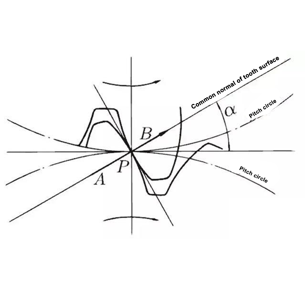
When the meshing state of tooth A and tooth B is viewed from the node:
Tooth A pushes point B on the node. At this time, the driving force acts on the common normal of tooth A and tooth B. In other words, the common normal is the direction of force and the direction of pressure, and α is the pressure angle.
The module (m), pressure angle (α) and number of teeth (z) are the three basic parameters of the gear, and the dimensions of each part of the gear are calculated based on these parameters.
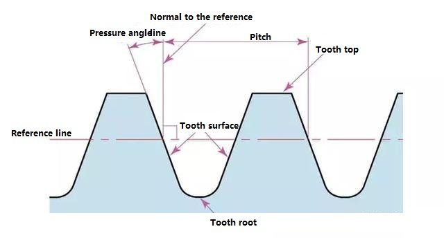
4) Tooth height and tooth thickness
The height of the gear tooth is determined by the module (m).

Total tooth height h=2.25m (=tooth root height + tooth top height)
Tooth top height (ha) is the height from the tooth top to the pitch line. ha=1m.
Tooth root height (hf) is the height from the tooth root to the pitch line. hf=1.25m.
The basis of tooth thickness (s) is half of the pitch. s=πm/2.
5) Gear diameter
The parameter that determines the size of the gear is the pitch circle diameter (d) of the gear. Only with the pitch circle as the basis can the pitch, tooth thickness, tooth height, tooth top height and tooth root height be determined.
Pitch circle diameter d=zm
Tooth top circle diameter da=d+2m
Tooth root circle diameter df=d-2.5m
The pitch circle cannot be seen directly in the actual gear, because the pitch circle is a hypothetical circle for determining the size of the gear.
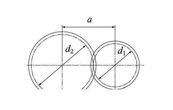
6) Center distance and tooth clearance
When the pitch circles of a pair of gears mesh tangentially, the center distance is half of the sum of the diameters of the two pitch circles.
Center distance a = (d1 + d2) / 2
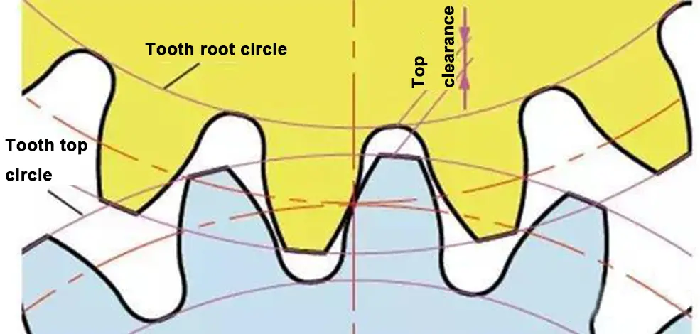
In the meshing of gears, tooth clearance is an important factor to achieve a smooth meshing effect. Tooth clearance is the gap between the tooth surfaces when a pair of gears mesh.
There is also clearance in the tooth height direction of the gear. This gap is called top clearance. Top clearance (c) is the difference between the root height of the gear and the top height of the matching gear.
Top clearance c=1.25m-1m=0.25m
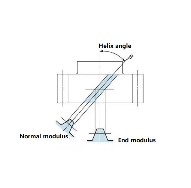
7) Helical gears
Gears made by twisting the teeth of spur gears in a spiral shape are called helical gears. Most of the geometric calculations for spur gears are applicable to helical gears. There are two types of helical gears, depending on their reference planes:
End face (axis right angle) reference (end face module/pressure angle)
Normal face (tooth right angle) reference (normal module/pressure angle)
The relationship between the end face module mt and the normal module mn is mt=mn/cosβ
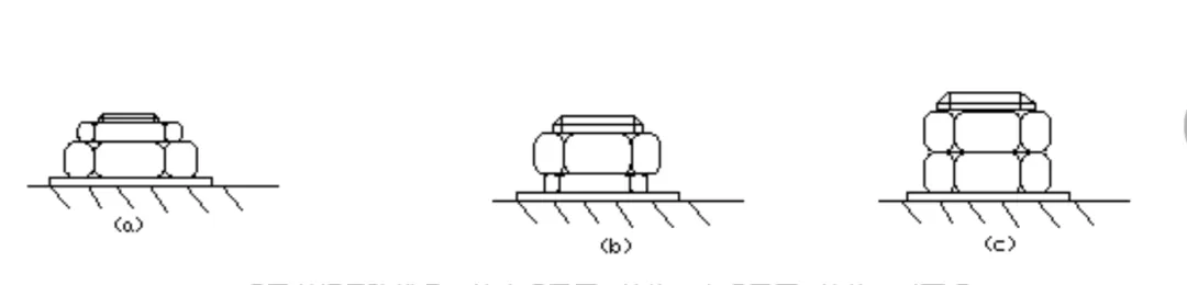
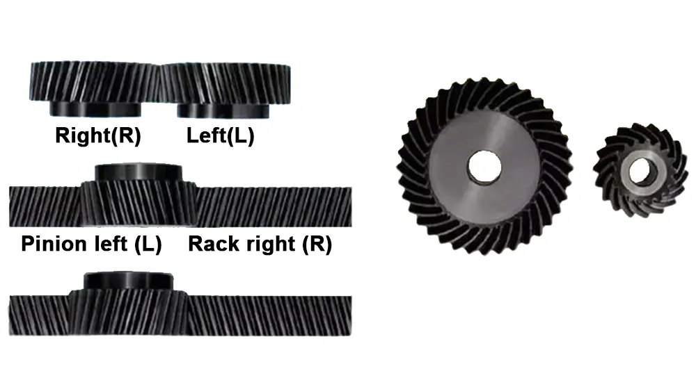
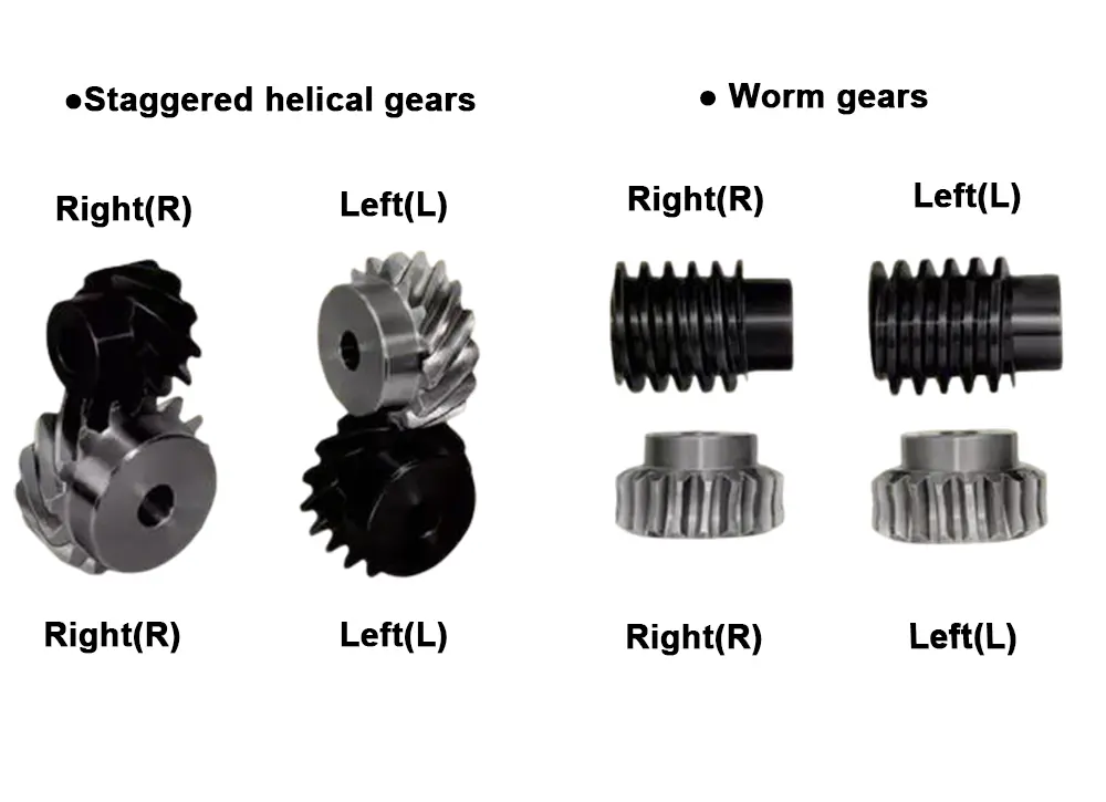
8) Spiral direction and fit
For gears with spiral teeth, such as helical gears and arc bevel gears, the spiral direction and fit are fixed. The spiral direction means that when the center axis of the gear points up and down, the direction of the gear teeth pointing to the upper right is [right-hand], and the direction of the gear teeth pointing to the upper left is [left-hand]. The fits of various gears are shown below.
Gear Assembly and Lubrication
Difficulties in Gear Assembly
1. High Precision Requirements
Gear assembly requires extremely high precision, and any slight error may cause the gear to operate poorly or be damaged. The robot must be able to make fine adjustments during the assembly process to ensure accurate docking of the gears. This high-precision requirement makes traditional positioning methods challenging.
2. Complex Geometry
Gears come in various shapes and sizes, especially in modern mechanical design, where gears often use complex tooth shapes and helical tooth structures. This diversity makes it difficult for robots to grasp and place them, especially in high-precision assembly, where even the slightest deviation may cause poor meshing of the gears.
3. Multiple Gears
Planetary gears consist of one or more external gears rotating around a central gear, similar to the orbit of a planet around the sun. The axis of the planetary gear is not fixed but is mounted on a rotatable bracket (planet carrier), so they have both self-rotation and orbital revolution.
Gear lubrication
Main quality and performance requirements for gear lubricants:
- Appropriate viscosity and good viscosity-temperature performance. The viscosity cannot be too low to form a sufficiently thick oil film, but the viscosity cannot be too high to avoid difficulty in starting at low temperatures.
- Good extreme pressure performance: Hyperbolic gears, curved bevel gears, spiral gears, and worm gear transmission gears are in line and point contact, bear a large load and a high speed, and have both sliding and rolling. The work is very demanding, so it must have good extreme-pressure performance.
- Good anti-oxidation stability: During the high-load and high-speed operation of gears, the working temperature of the oil is very high, and it is easy to oxidize and deteriorate, so the gear oil should have good anti-oxidation stability at high temperatures.
- Have good anti-corrosion performance: During the operation of gears, due to the action of oxidation and additives, the tooth surface is corroded, and the gears are prone to rust in the presence of water and oxygen. Therefore, the gear oil should have good anti-corrosion and anti-rust properties.
Choice of gear oil
Due to the differences in various gear transmission devices, the working pressure, speed, working temperature and working conditions of the gears are different. According to the specific situation, automotive gear oil and industrial gear oil of a certain viscosity grade and quality grade should be appropriately selected.
Automobile gear oil: At present, all countries in the world use API performance classification to classify vehicle gear oil into five categories according to quality: GL-1, GL-2, GL-3, GL-4, and GL-5.
Its viscosity grade is divided into six viscosity grades: 75W, 80W/90, 85W/90, 85W/140, 90 and 140. my country refers to the American SAE viscosity classification and divides automotive gear oil into seven grades: 70W, 75W, 80W, 85W, 90, 140 and 250.
Industrial gear oil: Industrial gear oil is divided into two types: closed gear oil and open gear oil.
The viscosity is divided into seven grades: 68, 100, 150, 220, 320, 460, 680
Closed gear oil: The quality classification is divided into six varieties: L-CKB, L-CKC, L-CKD, L-CKE, L-CKT, L-CKS
The viscosity is divided into five grades: 68, 100, 150, 220, 320
Gear Failure and Maintenance
Tooth surface pitting
- Causes and phenomena: Contact stress of the pulsating ring → tiny cracks on the tooth surface, the lubricating oil pressure rises under the extrusion of the gear → crack expansion, small pieces of metal peeling off → small pits (pitting)
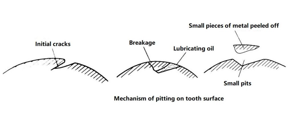
- Occurrence location: tooth root surface near the pitch line
- Occurrence occasion: closed transmission
- Preventive measures: increase tooth surface hardness, reduce surface roughness value, reasonably select lubricating oil viscosity and use positive angle displacement gear transmission

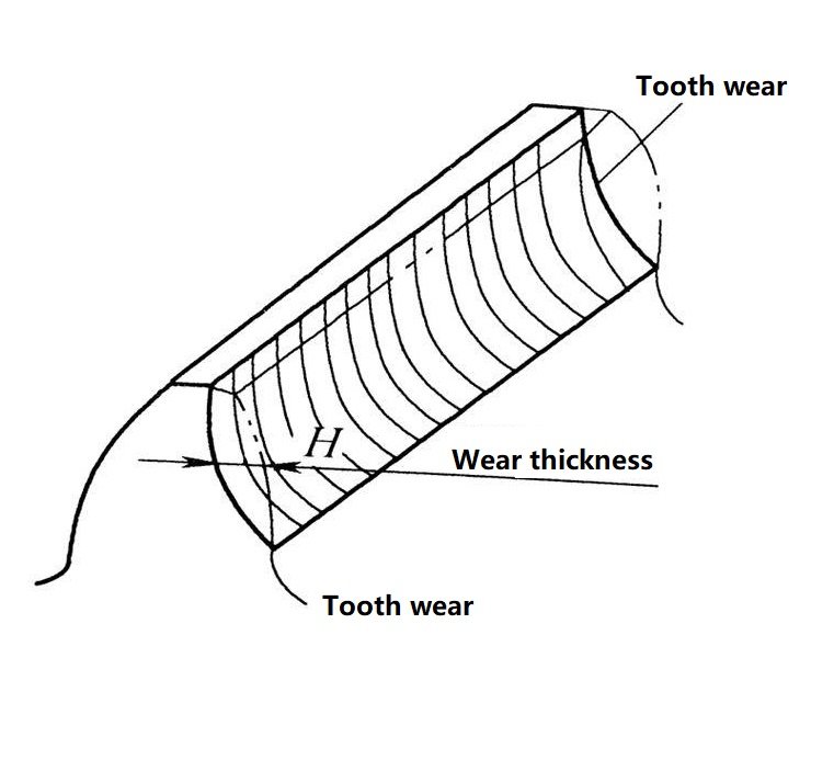
Tooth surface wear
1. Causes and phenomena: Iron filings and ash layers enter, relative sliding friction between meshing tooth surfaces causes wear, and the tooth shape becomes thinner
2. Occurrence: open transmission
3. Preventive measures: Use closed transmission, increase tooth surface hardness, reduce contact stress, reduce surface roughness value, and keep lubricating oil clean
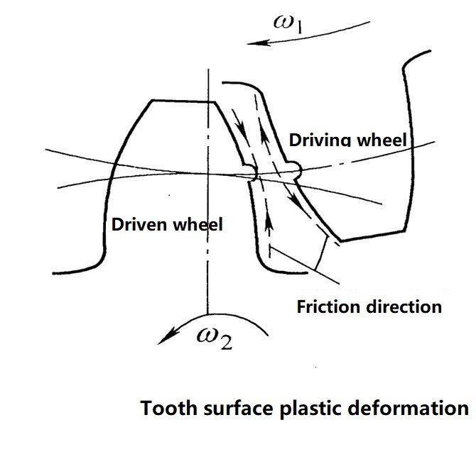
Tooth surface bonding
1. Cause: poor heat dissipation at high speed and heavy load, excessive pressure at low speed and heavy load, which destroys the oil film and causes metal welding and bonding.
2. Occurrence location: tooth top surface close to the pitch line.
3. Occurrence occasion: high-speed, low-speed and heavy-loaded gears.
4. Preventive measures: suitable lubricating oil, increase hardness, reduce surface roughness value, use gear materials with strong anti-bonding ability.
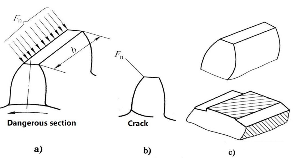
Tooth breakage
1.Cause: variable load (fatigue, overload)
2.Consequences: failure to transmit normally, or even major accidents
3.Occurrence: open gear transmission and hardened closed gear transmission
4.Preventive measures: select appropriate modulus and tooth width, use appropriate materials and heat treatment processes, and reduce stress concentration at the tooth root.
Daily Maintenance and Care
1.Regular inspection
a. Check whether the gearbox has abnormal vibration and noise
b. Check whether the gear meshing surface has abnormal wear or cracks
2. Maintain good lubrication
a. Regularly replace lubricating oil or grease
b. Use oil that meets the manufacturer’s requirements
c. Check the oil level, oil quality, and whether the seals are aging and leaking
3. Keep clean
a. Prevent dust and metal chips from entering the gearbox
b. Clean the oil circuit and filter regularly
4. Load management
a. Avoid overload operation and avoid sudden impact
b. Reasonably set the start and stop procedures
5. Regular inspection and calibration
a. Regularly perform professional inspections, such as gear meshing clearance, center distance, etc.
b. Grind the tooth surface or replace worn gears when necessary
c. Check the bearings and connectors to ensure the centering accuracy
Gear Selection Principles
Power, speed, and torque demand analysis
●Power: First, determine the power to be transmitted in order to select the appropriate modulus, material, and gear size to ensure sufficient load-bearing capacity.
●Speed: According to the input and output speed requirements, calculate the transmission ratio and reasonably select the gear tooth number combination to avoid poor tooth shape or unstable meshing due to too few teeth.
●Torque: Select the strength grade and heat treatment requirements of the gear according to the working torque to prevent failures such as broken teeth and pitting caused by overload.
Working conditions (load, temperature, environment)
●Load nature: Consider whether it is a constant load or an impact load. If there are frequent starting and braking conditions, materials with good toughness and high surface hardness should be selected.
●Temperature conditions: In high-temperature environments, the heat resistance of the material and the stability of the lubricating oil need to be considered, in low-temperature environments, the embrittlement of the material or lubrication failure should be prevented.
●Working environment: If working in a humid, dusty or corrosive environment, rust-proof and corrosion-resistant materials need to be selected, and the sealing structure should be considered.
Noise and vibration requirements
● For noise-sensitive occasions (such as home appliances and service robots), helical gears, spiral gears or high-precision plastic gears with smooth transmission and smooth meshing should be selected.
● For high-speed transmission, it is recommended to use the grinding process to improve meshing accuracy and reduce noise and vibration.
Cost and processability
● Under the premise of ensuring performance, mature, standardized gears should be given priority to reduce customization costs and delivery time.
● For mass production, plastic gear mold molding costs are low and are suitable for light load and low noise scenarios.
● High-strength alloy steel gears should be used for high-power occasions. Although the processing cost is high, it can ensure safety and reliability.
Standardization and versatility
● Gears that meet national or international standards (such as ISO, DIN, and AGMA standards) should be used first to facilitate later replacement and maintenance.
● Combined with actual use conditions, universal modulus, pressure angle and standard tooth width should be selected to avoid the difficulties of customized processing caused by non-standard gears.
● Consider the standardization of cooperation with other transmission parts (shafts, bearings, keyways) to ensure the consistency of the whole machine assembly and the convenience of later maintenance.
Advantages and Disadvantages of Gears
Advantages of Gear Transmission
High Transmission Efficiency
Gear transmission belongs to meshing transmission, with low energy loss and efficiency generally reaching more than 95%, which is suitable for occasions requiring efficient transmission.
Accurate and stable transmission ratio
Gear transmission relies on tooth surface meshing and constant transmission ratio and can achieve accurate speed and position transmission, which is suitable for precision machinery and automation equipment.
Wide range of applications
It can be used on a variety of occasions, from low speed and high torque to high speed and low torque, the transmission power range is from a few watts to hundreds of megawatts.
Compact structure and long service life
Compared with belt transmission and chain transmission, gear transmission has a more compact structure, small size, and longer service life under good lubrication conditions.
A variety of complex movements can be realized
Through different gear combinations, it can realize multiple functions, such as deceleration, speed increase, reversing, diversion, and confluence, with high flexibility.
Disadvantages of Gear Transmission
High manufacturing and installation requirements
Gear transmission has high requirements for tooth processing accuracy, meshing clearance, and center distance consistency, and the processing and assembly costs are high.
Strict lubrication requirements
a. The tooth surfaces are in rolling and sliding composite contact and must be well lubricated. Poor lubrication can easily lead to wear, bonding, and even broken teeth.
Cannot be transmitted over long distances
a. Gear transmission is suitable for occasions where the distance between shafts is relatively close. If long-distance transmission is required, a belt drive or chain drive must be used.
Noise and vibration are easily generated during operation
a. When meshing at high speed, if the gear accuracy or lubrication is not good, it may generate large noise and vibration, especially spur gears.
Sensitive to overload impact
a. Gear transmission generally does not have overload adaptive capability, and it is easy to cause tooth surface damage or broken teeth when the impact load is large.
Special Comparison and Application
Helical Gears vs. Helical Gears
| Item | Spiral Bevel Gear | Helical Gear |
| Tooth Shape | The tooth trace is a helical curve, spirally wrapped around the gear’s cylindrical surface. | The tooth trace is a straight line but set at an angle to the gear axis. |
| Shaft Arrangement | Commonly used for intersecting shafts (e.g., 90° cross shafts) to transmit power at various angles in space. | Mainly used for parallel shaft transmission. |
| Meshing Characteristics | Larger relative sliding between tooth surfaces, progressive engagement. | Higher overlap ratio of tooth surfaces, smoother meshing. |
| Manufacturing Difficulty | More complex tooth shape and installation requirements. | Relatively easy to manufacture and widely standardized. |
Comparison between plastic gear nylon (MC901) and POM
| Item | Nylon (MC901) | POM (Polyoxymethylene) |
| Material Type | Cast Nylon (MC901), a type of engineering plastic known for high toughness and wear resistance. | Polyoxymethylene, also known as acetal, an engineering thermoplastic with excellent dimensional stability. |
| Mechanical Strength | High strength and toughness, good impact resistance. | High stiffness and hardness, lower impact resistance compared to nylon. |
| Wear Resistance | Excellent wear resistance and self-lubricating properties. | Very good wear resistance and low friction coefficient. |
| Water Absorption | Higher water absorption, which may affect dimensional stability. | Low water absorption, maintains dimensions well in humid environments. |
| Dimensional Stability | Good, but sensitive to moisture. | Excellent dimensional stability, less affected by moisture. |
| Processing | Easier to machine, can be cast into large parts. | Easy to machine, widely used in precision parts. |
| Typical Applications | Gears, bushings, pulleys, and wear-resistant parts in heavy-duty conditions. | Gears, precision mechanical parts, bearings, and sliding elements requiring high dimensional accuracy. |
Gear Future Development Trends
Electrification, flexibility, intelligence and lightweight are the development trends of future products, which are both challenges and opportunities for traditional gear companies.
Electrification: The electrification of power has brought challenges to traditional gear transmission. The crisis it brings is: on the one hand, traditional gear transmission is upgraded to high speed, low noise, high efficiency, high precision and long life with simpler and lighter structure, and on the other hand, it faces the subversion of electric direct drive without gear transmission. Therefore, traditional gear transmission companies should not only study how to meet the requirements of electrification for gear transmission noise control at ultra-high speed (≥15000rpm), seize the opportunities for the growth of new transmissions spawned by the current explosive growth of electric vehicles, but also pay close attention to the revolutionary threats brought by future gearless electric direct drive technology and electromagnetic transmission technology to traditional gear transmission and gear industry.
Flexibility: In the future, market competition will become increasingly stimulating, and the demand for products will tend to be diversified and personalized, but the demand for a single product may not be very large. As a basic industry in the manufacturing industry, the gear industry will face many downstream fields and put forward higher requirements for the diversity and efficiency of product manufacturing. Therefore, enterprises must establish a flexible production system and complete the batch production tasks of different varieties through equipment adjustment on the same production line, which can not only meet the diversified requirements of multiple varieties but also minimize the downtime of the equipment assembly line, realize flexible production, and build the core competitiveness of the enterprise.
Intelligence: The wide application of control technology in machines has enabled machines to be automated, the comprehensive application of control technology, information and communication technology, and network technology has enabled machines and manufacturing to be intelligent. For traditional gear manufacturing companies, the challenge is how to integrate electrical engineering, electronic engineering, control technology, network technology, and form intelligence.
Lightweight: Lightweight and high-strength materials, structural weight reduction, and surface modification and strengthening require cross-industry cooperation and advanced simulation technology.
Gear FAQs
How to choose a factory to make custom gear?
A good gear factory is not only about processing but also should be able to provide professional selection suggestions, tooth shape design optimization, and material and heat treatment solutions to help customers save costs and increase service life.
1. Processing accuracy
Check whether the factory has key equipment, such as high-precision CNC gear grinding machines, gear hobbing machines, and testers, and whether it can meet the accuracy level you need (such as DIN 6, DIN 8, etc.).
2. Material and heat treatment capabilities
Gear performance depends largely on the quality of materials and heat treatment. Excellent factories will use certified materials (such as alloy steel, carburizing steel, and high-performance plastics) and have complete heat treatment processes such as carburizing quenching, tempering, and surface hardening.
It is more secure to choose suppliers that have passed ISO 9001 or IATF 16949 certification.
Complete testing process, such as a tooth shape tester, hardness tester, three-coordinate measuring machine, etc
Whether to provide factory inspection reports, material certificates and necessary third-party inspections.
4. Customization and batch capabilities
According to your needs, check whether the factory supports multiple batches: single samples, small batch trial production, to large batch production can respond flexibly.
Whether it can quickly make samples, short delivery time and handle urgent orders.
5. Communication and service
Is the project communication professional and efficient? Are there technical engineers who can directly contact?
Is the production progress and quality issues transparent, and is the after-sales response timely?
6. Cost and delivery time
Is the price reasonable and transparent, and are there any hidden costs?
Whether it provides multiple transportation and delivery options and whether it can deliver on time, especially the cross-border supply capabilities and customs clearance experience.
What should I do if the gears are seriously heated when meshing?
Gears generate heat when meshing at high speed or high load. If the heat is too large, it may cause the lubricant to deteriorate and the tooth surface to glue.
Solution:
● Check whether the appropriate lubricant is selected and ensure sufficient lubrication.
● Check whether the meshing clearance is too small and adjust it to a reasonable range.
● If conditions permit, add oil cooling devices or strengthen heat dissipation and ventilation.
How to judge whether the gear needs to be replaced?
The following points can judge it:
● Severe pitting, peeling or cracking on the tooth surface.
● Obvious wear on the tooth top or root, poor meshing.
● Abnormal noise and significantly increased vibration during operation.
● Obvious gap, tooth hitting or tooth skipping.
If there are any of the above problems, it is recommended to replace it in time to avoid further damage.
What should I do if the gear meshing noise is too loud?
Excessive gear noise is usually related to the following factors: insufficient meshing accuracy, improper installation, poor lubrication or workload fluctuations.
Solution:
● Check whether the machining accuracy of the gear meets the standard. If necessary, grind or replace high-precision gears.
● Adjust the axis distance to ensure that the meshing clearance is appropriate and avoid being too tight or too loose.
● Use high-quality lubricating oil to keep the tooth surface fully lubricated and reduce direct metal contact.
● If the structure allows, helical gears or spiral gears can be used instead of spur gears to reduce the vibration and noise caused by impact meshing.
How to extend the life of gears?
In order to make gears more durable, we should start from design, material selection, and processing to daily use and maintenance:
● Reasonable selection: Select the appropriate gear type and material according to the actual load, speed and environment.
● High-quality manufacturing: Use precision machining and necessary heat treatment processes (such as carburizing and quenching) to improve the hardness and wear resistance of the tooth surface.
● Correct installation: Ensure that the gear shaft is well aligned, the meshing clearance is correct, and avoid eccentric loading.
● Regular lubrication: Choose suitable lubricating oil or grease, and check the oil quality and oil quantity regularly.
● Regular inspection: Repair or replace wear and cracks in time to prevent the expansion of faults.
Can plastic gears replace metal gears?
Plastic gears (such as nylon and POM) can replace metal gears on some occasions, especially when there are strict requirements on noise, weight and cost:
Applications: small load, medium and low speed, high noise requirements, relatively clean working environment (such as household appliances, light-load robot transmission).
Restrictions: The load-bearing capacity and high-temperature resistance of plastic gears are worse than those of metal gears, and they are not suitable for industrial power transmission with heavy loads, high speeds, and large impact loads.
Suggestion: Before replacement, the load-bearing capacity must be fully verified, and the effects of thermal expansion, water absorption, etc., must be considered.
Conclusion
Gears, as one of the core components of mechanical transmission, are widely used in various equipment and automation systems. Different types of gears (such as spur gears, helical gears, spiral gears, bevel gears, etc.) have their structural characteristics, applicable scenarios, advantages and disadvantages. When selecting, it is necessary to comprehensively consider factors such as power, speed, torque, working environment and noise. At the same time, reasonable material selection and an advanced heat treatment process can significantly improve the service life and operating stability of gears.
In actual use, correct installation, timely lubrication and standardized daily maintenance are the keys to ensure efficient operation of gears and reduce the risk of failure. Faced with various application scenarios, such as robot transmission, small household appliances or industrial reducers, plastic gears and metal gears have their advantages, and they need to be reasonably selected according to load and working conditions.
In addition, with the improvement of industrial automation and high-precision requirements, it is particularly important to choose a custom gear factory with strong technical capabilities, perfect quality management and reliable delivery. Through scientific selection, standardized use and regular maintenance, the performance of gears can be maximized to ensure the long-term, safe and stable operation of mechanical equipment.