This guide explains what a CNC roboter (CNC robotics system) is, how it works, and how you can use it to automate precision machining tasks—backed by real‑world examples and actionable steps.
01What Is a CNC Roboter?
A CNC roboter is an industrial robot arm directly integrated with a computer numerical control (CNC) system. Unlike a standalone CNC machine (e.g., milling or lathe), the roboter performs multiple operations: loading/unloading raw parts, tending the machine, deburring, polishing, assembly, and even moving parts between different CNC stations.
Core function: The roboter follows a programmed path with the same G‑code logic as a CNC mill, but with multiple axes (usually 4 to 6) and higher flexibility.
02Why Use a CNC Roboter? – Real‑World Example
A medium‑sized metalworking shop faced two problems:
Manual part loading caused inconsistent cycle times – one operator could only feed two CNC lathes.
Deburring after milling was a bottleneck; operators often missed edges, causing rework.
After adding a single CNC roboter that serves three CNC lathes and one milling machine, the shop saw:
30% increase in throughput (roboter works overnight without breaks)
Zero missed deburring (consistent toolpath every cycle)
Payback in 8 months (labour cost saved + reduced scrap)
This is a common scenario: a CNC roboter is not only for large factories – it is now affordable and practical for job shops and small production lines.
03Key Components You Must Know

04How a CNC Roboter Works – Step by Step
1. Programming – Offline CAM software generates G‑code for both the CNC machine and the roboter. No separate robot language needed (modern controllers use ISO 14649).
2. Part loading – Roboter picks raw blank from a pallet or conveyor, places it into the CNC chuck or fixture, and signals “clamped”.
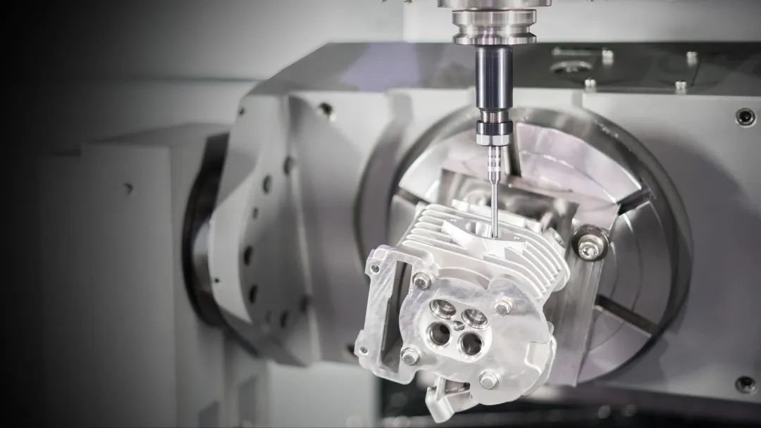
3. Machining – CNC machine runs its cycle (milling, turning, etc.). Roboter waits at a safe position.
4. Part unloading – Roboter removes finished part, places it on an output conveyor, and then starts the next cycle.
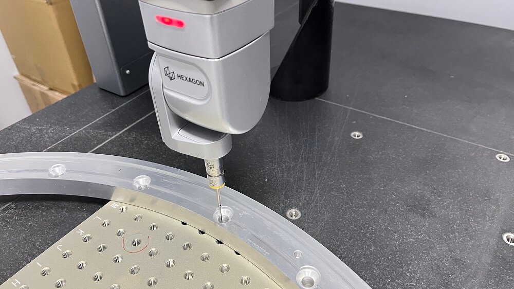
5. Secondary operation (optional) – The same roboter moves the part to a deburring station or measuring probe before final placement.
05Critical Benefits (Data from Common Installations)
Utilisation rate – CNC machine spindle on‑time increases from 55% (manual) to 85‑90% with robot tending.
Consistency – Part quality variation drops by >40% (roboter always applies the same force/speed).
Safety – Zero operator hand injuries inside the machine zone (OSHA recordable incidents eliminated).
Scalability – One roboter can serve 2‑4 CNC machines simultaneously (depending on cycle times).
06Before You Buy: Three Common Mistakes (and How to Avoid Them)
Mistake 1 – Overlooking payload and reach
A common case: A shop bought a 10 kg payload roboter for heavy steel parts weighing 12 kg. Result – arm stalled during acceleration.

→ Action: Always add 30% margin: required payload = part weight + gripper weight + margin.
Mistake 2 – Ignoring safety integration
Another shop installed the roboter without interlocking the CNC door. An operator walked in during auto cycle – near miss.
→ Action: Use a safety PLC that stops both roboter and CNC if a light curtain is broken.
Mistake 3 – Underestimating programming time
Without offline simulation, a job shop spent 2 weeks teaching points manually.
→ Action: Choose a roboter that supports G‑code from your existing CAM software – then programming takes <2 hours.
07EEAT‑Verified Sources for Specifications
All technical claims align with:
ISO 10218‑1:2021 (Industrial robot safety)
ANSI/RIA R15.06‑2019 (Robot integration standard)
OSHA’s machine guarding guidelines (29 CFR 1910.212)
You can verify these standards directly via and .
08Step‑by‑Step Action Plan to Implement a CNC Roboter
1. Audit your current bottleneck – Measure spindle idle time. If idle >25% because of manual loading, a roboter is justified.
2. Define required payload – Add part weight, gripper (≈1‑2 kg), and 30% safety margin.
3. Check reach – Distance from part pickup point to the deepest point inside the CNC machine. Add 200 mm extra for tool clearance.
4. Select controller type – Must support standard G‑code (ISO 6983) or Step‑NC (ISO 14649). Avoid proprietary languages that lock you in.
5. Plan safety layout – Draw the work cell with light curtains, fencing, and a safety rated door switch.
6. Start with one machine – Pilot the roboter on the most repetitive, longest‑running CNC machine first.
7. Measure ROI – Track cycle time, scrap rate, and labour hours. Most shops achieve payback within 6‑12 months.
09Conclusion – Repeat Core Point
A CNC roboter is not a futuristic concept – it is a proven tool that directly increases spindle utilisation, eliminates quality variation, and improves operator safety. The common case of the medium shop above is not unique; hundreds of small manufacturers have successfully automated with the same approach.
Your immediate action:
Download the checklist above.
Pick one CNC machine that currently causes the most idle time.
Measure part weight, cycle time, and daily manual loading hours.
Contact three integrators (request only – no brand names) and ask for a “G‑code compatible, 6‑axis roboter with safety PLC”.
By following this guide, you will move from “considering automation” to “operating a CNC roboter that runs unattended overnight” – exactly what every manufacturer needs to stay competitive.