Quick answer:
CNC programming codes are the standardized commands that tell machine tools exactly how to move, cut, and finish parts. G-codes control motion paths while M-codes handle machine functions like cooling or tool changes. Understanding these codes is essential for verifying program accuracy before production begins. Incorrect interpretation leads to costly collisions and scrapped components.
Buyers often face uncertainty when reviewing submitted CNC programs for complex geometries. You need to ensure the code structure matches your specific machine controller’s capabilities. Misaligned codes can cause unexpected stops or dimensional errors during execution.
This guide clarifies standard ISO codes used in most modern machining centers. We outline key command types, common errors, and verification steps. YPMFG provides engineering reviews to validate code compatibility with your equipment.
Core Function of CNC Codes
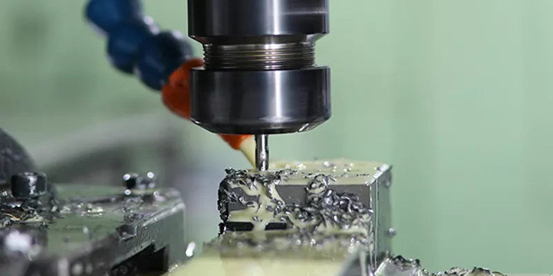
CNC codes serve as the direct interface between design intent and physical production. They translate digital models into precise mechanical movements along multiple axes. Each line of code instructs the spindle speed, feed rate, and travel position.
These instructions rely on a universal language known as the ISO standard. Most manufacturers adhere to this framework to ensure interoperability across different machines. Deviations from standard codes require custom post-processing or manual adjustments.
Without proper coding, automated machining cannot achieve consistent quality or repeatability. Errors in coordinate logic often result in tool crashes or material waste. Understanding the basics helps procurement teams evaluate technical proposals accurately.
Essential G-Codes for Motion Control
G-codes dictate the geometric path the cutting tool follows during operation. G00 commands rapid positioning moves that do not involve cutting material. These fast movements connect starting points to reduce non-cutting time efficiently.
G01 controls linear interpolation at a specified feed rate for straight cuts. It is fundamental for milling flat surfaces or drilling precise holes. The machine maintains strict alignment between the start and end coordinates.
G02 and G03 manage clockwise and counter-clockwise circular interpolation respectively. These codes are critical for creating arcs, contours, and rounded features. Accuracy here depends heavily on radius parameters and center point definitions.

Critical M-Codes for Machine Operations
M-codes manage auxiliary functions that support the primary cutting process. M03 starts the spindle rotation in a clockwise direction for standard machining. This command must activate before any cutting motion occurs to prevent damage.
M08 activates the coolant flow to reduce heat and remove chips effectively. Proper cooling extends tool life and improves surface finish quality significantly. Buyers should verify if their application requires flood or mist cooling systems.
M30 signals the end of the program and resets the machine controller. It ensures the machine returns to its safe home position automatically. Skipping this step may leave the machine in an undefined state.
Common Programming Errors and Risks
Incorrect coordinate values are a frequent source of production failures. Missing decimal points or swapped axis orders can shift parts by millimeters. Such errors often go unnoticed until the first trial run confirms them.
Ignoring tool length offsets leads to inaccurate depth control and poor finishes. The machine assumes all tools have identical dimensions without proper compensation. This oversight causes deep cuts or insufficient material removal depending on the tool.
Using unsupported modal states confuses the controller’s internal logic. For example, forgetting to cancel a previous circular interpolation command affects subsequent lines. Always reset specific modes after completing specialized operations to maintain safety.
Verification Steps Before Production
Review the code against the original CAD model geometry for alignment. Check that all referenced tools match the available inventory in the magazine. Discrepancies here delay setup and increase operational costs unnecessarily.
Simulate the program path using CAM software to detect potential collisions. Visualizing the tool movement reveals unreachable areas or unsafe rapid moves. This digital check prevents physical damage to expensive machine components.
Confirm feed rates and spindle speeds suit the selected workpiece material. Aluminum requires different parameters than stainless steel for optimal performance. Incorrect settings cause excessive wear or substandard surface textures.
Material Considerations in Coding Strategy
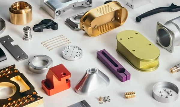
Different materials react uniquely to cutting forces and thermal generation. Hardened steels demand slower feed rates and higher torque settings. Programming codes must reflect these adjustments to maintain tool integrity.
Aluminum alloys allow for aggressive machining parameters due to their softness. However, chip evacuation becomes critical to prevent recutting and surface scoring. Code sequences should include frequent retract moves to clear debris effectively.
Composite materials generate static electricity and abrasive dust during cutting. Specialized codes may be needed to control vacuum extraction systems simultaneously. Verify compatibility between standard G-codes and auxiliary handling requirements.
Impact on Cost and Efficiency
Efficient code structure directly reduces cycle times and labor expenses. Optimized tool paths minimize air cutting and unnecessary machine idle time. Shorter cycles allow for higher output volumes within fixed shifts.
Poorly written code increases scrap rates and rework requirements significantly. Material waste accumulates quickly when dimensional accuracy is compromised repeatedly. High rejection rates erode profit margins and damage client trust.
Standardized coding practices simplify training for new operators and programmers. Consistent formats reduce communication gaps between design and production teams. This alignment accelerates project timelines and improves overall workflow reliability.
How YPMFG Supports Your Projects
YPMFG offers comprehensive engineering assessments for submitted CNC programs. Our experts analyze code logic to identify inefficiencies or safety risks. You receive detailed feedback on potential improvements before mass production starts.
We provide custom solutions tailored to your specific machine configurations. Whether you use Fanuc, Siemens, or Haas controllers,we ensure compatibility. Our team verifies that all G-codes and M-codes function correctly.
Request a quote for our technical review services to mitigate risks. Send your NC files for immediate evaluation by senior engineers. Secure your supply chain with validated, error-free programming standards.
Common Questions About CNC Codes
What is the difference between absolute and incremental programming?
Absolute programming uses fixed origin coordinates for every movement command. Incremental programming calculates positions relative to the previous location. Absolute mode is generally safer for complex multi-step operations.
Can I mix different code standards in one file?
Mixing standards like ISO and proprietary formats causes controller confusion. Most modern machines reject non-standard syntax during execution checks. Stick to one consistent standard throughout the entire program file.
Why do some codes require preparatory functions first?
Preparatory functions set the context for subsequent motion commands. For instance, selecting a plane must precede circular interpolation commands. Skipping these steps leads to incorrect axis interpretation and errors.
How do I handle tool wear in long programs?
Include compensation commands that adjust lengths dynamically during cycles. Monitor wear sensors and update offset tables regularly. Automated adjustments maintain precision without stopping the machine frequently.
Is post-processing necessary for all CNC codes?
Post-processing translates generic code into machine-specific instructions reliably. It ensures syntax compatibility with your particular controller’s requirements. Skipping this step often results in unreadable or erroneous machine input.
Need Help Selecting the Right CNC Approach?
Accurate CNC programming codes are vital for maintaining quality and reducing waste. Understanding G-codes and M-codes allows buyers to verify technical submissions effectively. Proper verification prevents costly production errors and ensures component consistency.
Partner with experienced manufacturers who prioritize code validation and engineering support. YPMFG helps you navigate technical complexities with professional reviews and custom solutions. Contact us to send your specifications for an expert assessment today.