CNC Milling and Turning: Your Complete Guide to Precision Machined Parts
This guide provides a direct, practical overview of CNC milling and lathe turning for producing precision metal and plastic parts. Whether you are an engineer, buyer, or designer, you will learn the core differences between these processes, key design rules, material selection, and how to get high-quality results. The goal is to give you the exact information needed to successfully source or manufacture CNC machined components.
What Are CNC Milling and Turning? The Core Difference
CNC machining uses computer-controlled tools to remove material from a solid block (workpiece) to create a finished part. The two primary methods are milling and turning, and they serve different purposes.
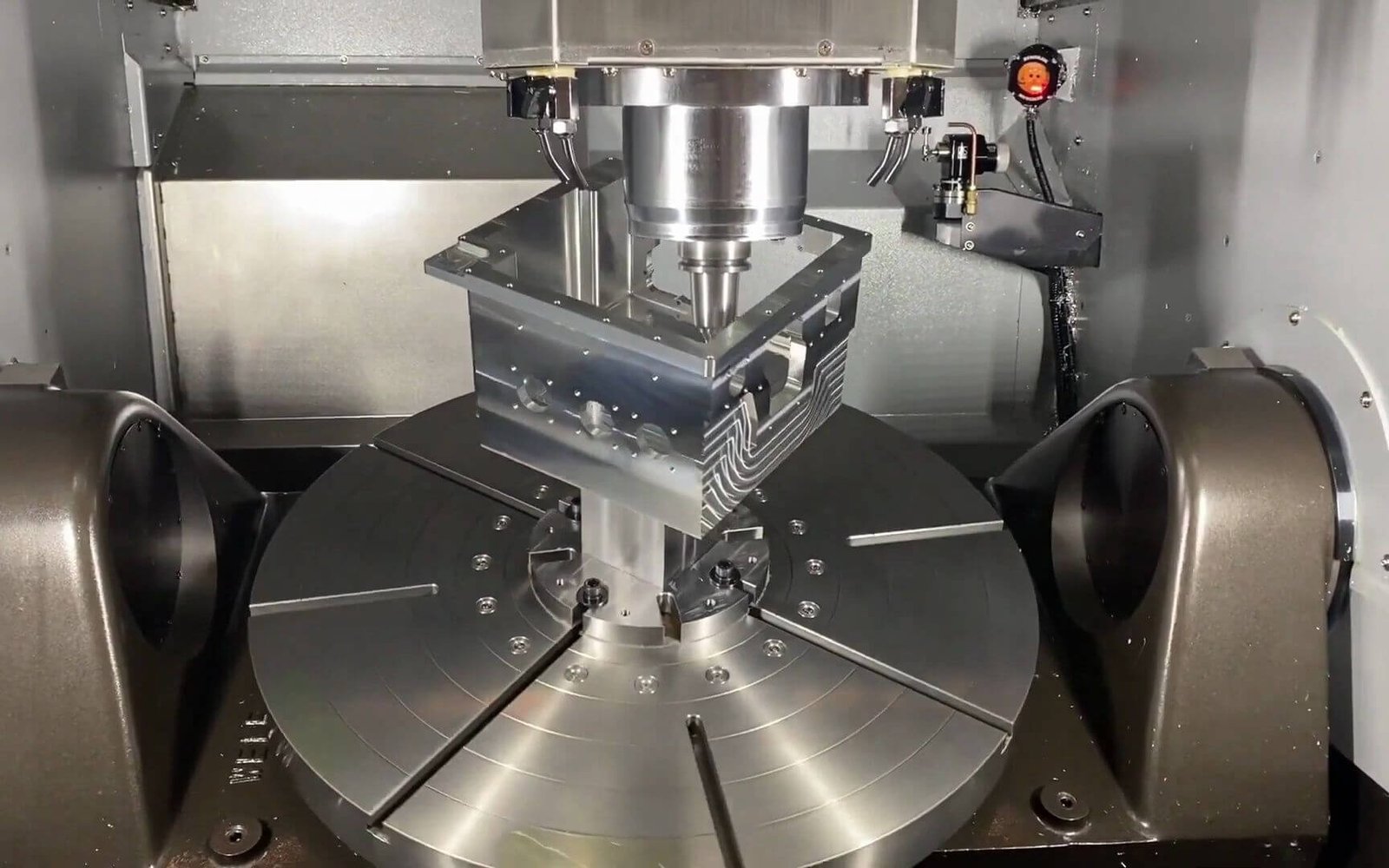
CNC Milling: The cutting tool spins while the workpiece stays clamped on a moving table. This is ideal for creating flat surfaces, slots, pockets, holes, and complex 3D shapes. Think of parts like engine blocks, brackets, enclosures, or any component with features on multiple sides.
CNC Turning (Lathe): The workpiece spins rapidly while a stationary cutting tool moves along it. This is perfect for cylindrical parts. Think of shafts, bushings, pins, threaded rods, and discs. Modern CNC lathes can also perform live tooling (milling operations on a spinning part).
When to Use Milling vs. Turning (Real-World Examples)
Choosing the right process saves time and cost. Here are common scenarios:
Case: A Drive Shaft for a Small Motor. You need a part with precise diameters, a keyway, and threads on both ends. The primary operation is turning to form the cylinder, steps, and threads. The keyway (a flat slot) requires milling or a live tooling cycle on a lathe. The most efficient method is a CNC lathe with live tooling or a secondary milling operation.
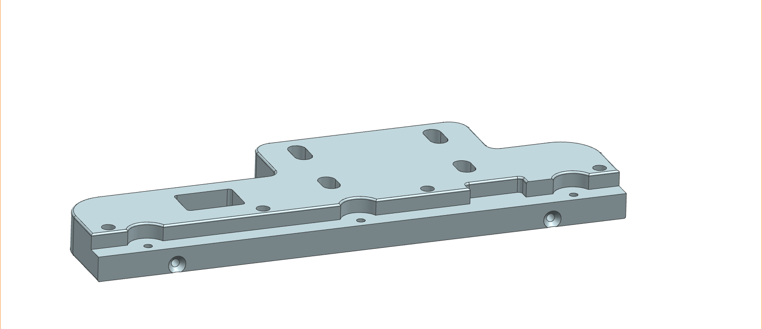
Case: A Custom Aluminum Bracket. The part has flat mounting surfaces, several drilled and tapped holes, and a complex curved profile. This is a pure milling job. Starting with a rectangular block, a CNC mill will face the top, drill holes, and contour the shape.
Case: A Flanged Bushing. This part has a cylindrical body with a hexagonal flange and a cross-hole. Turning creates the cylinder and bore. The hexagonal flange and cross-hole require milling (or live tooling). The smart solution is turning first, then milling, or using a multi-axis lathe.

Critical Design Rules for High-Quality CNC Parts
To ensure your parts are machinable, accurate, and cost-effective, follow these proven rules:
1. Hole Depth and Diameter
Rule: For milling, the depth of a hole should not exceed 4 times its diameter (4xD) for standard tools. For turning, a depth of 6xD is common.
Why: Deeper holes require specialized tooling, increasing cycle time and cost.
Solution: Design holes as shallow as functionally possible. If a deep hole is needed, specify it clearly and be prepared for added cost.
2. Internal Corners (Radius)
Rule: All vertical internal corners in a milled pocket must have a radius. The minimum radius is equal to the cutting tool’s radius (typically 1/16″ or 1.5mm). A sharp 90-degree corner is impossible to machine directly.
Example: If you need a square pocket, specify a corner radius of 1.5mm or larger. For a true sharp corner, a secondary EDM (electrical discharge machining) process is required, which is expensive.
Solution: Use the largest radius your design allows. For the floor of a pocket, a small radius (0.5mm) is fine because the bottom of the tool is flat.
3. Wall Thickness
Rule: For metals, minimum wall thickness is 0.5mm (0.02″). For plastics, it’s 1.0mm (0.04″).
Why: Thin walls vibrate during machining, causing inaccuracy and potential part breakage.
Solution: Increase wall thickness where possible. For very thin features,consider reducing cutting forces or adding temporary support.
4. Threads and Tapped Holes
Rule: For holes under M6 (6mm diameter), use standard coarse threads (e.g., M3x0.5, M4x0.7, M5x0.8, M6x1.0). Minimum thread depth is 1.5x the diameter.
Why: Very fine threads or shallow depths are weaker and harder to machine consistently.
Solution: Specify standard threads. For blind holes (not through), leave at least 3-4 threads of unthreaded space at the bottom for the tap to clear.
Standard Materials for CNC Machining (With Key Properties)
Material selection directly impacts cost, strength, and machinability. Below are the most common choices:
Critical Quality Factors: Tolerances and Surface Finish
Every part drawing includes tolerances (allowable variation). Standard CNC machining holds:
General Tolerances: ±0.125mm (±0.005″) for features up to 150mm.
Precision Tolerances: ±0.025mm (±0.001″) or tighter with specialized tooling and inspection.
Surface Finish: Standard machined finish is 3.2 µm Ra (125 µin). A finer finish (0.8 µm Ra / 32 µin) is achievable with slower feeds and different tools.
Actionable Advice for Getting Your Parts Made
Follow these steps to ensure success:
1. Provide a Complete Drawing: Include all views, dimensions, tolerances, material callout, and surface finish requirements. A 3D CAD file (STEP or IGES) plus a 2D PDF drawing is the industry standard.
2. Define Critical Features: Clearly mark which dimensions are critical. Use geometric dimensioning and tolerancing (GD&T) if possible.
3. Avoid Over-Tolerancing: Only apply tight tolerances where absolutely necessary for fit or function. Every tight tolerance increases cost.
4. Communicate Early: Tell your machinist about any assembly requirements, heat treatment, or post-processing (anodizing, plating, painting) before they start programming.
5. Request a Design for Manufacturability (DFM) Review: A good machining partner will review your design and suggest changes to lower cost or improve quality at no extra charge.
Repeat Core Point: The most successful CNC projects start with a clear understanding of milling versus turning, follow basic design rules for radii and wall thickness, specify standard materials and reasonable tolerances, and involve the machinist early in the process.
Final Action Step: Before finalizing your design, review each feature against the rules above: check hole depths, internal radii, wall thicknesses, and thread standards. Then, contact your chosen machining service with a complete drawing and a request for a DFM analysis. This approach consistently delivers parts that are accurate, on time, and at the lowest possible cost.