CNC machining Inconel parts is challenging but absolutely achievable with the right approach. Inconel, a nickel-chromium superalloy, is known for its high strength, excellent heat resistance, and severe work-hardening tendency—properties that make it extremely difficult to cut. However, by applying proven tooling strategies, optimized cutting parameters, and proper coolant methods, you can produce precise, high-quality Inconel parts reliably.
01Why Inconel Is Difficult to Machine
Inconel’s unique characteristics create three primary machining obstacles:
Rapid work hardening – The material hardens immediately under the cutting edge, causing premature tool failure if cuts are too light.
Low thermal conductivity – Heat concentrates at the cutting zone instead of dissipating into the chip, leading to extreme temperatures that degrade tool material.
High strength at elevated temperatures – Inconel retains its hardness even when red-hot, accelerating abrasive wear on cutting tools.
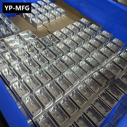
A common scenario: A machine shop receives an order for 20 Inconel 718 flanges. Using standard carbide tools and parameters meant for stainless steel, they experience tool breakage after just two parts. This is not a machine issue—it is a strategy issue.
02Proven Tooling Solutions for Inconel
1. Carbide Grades & Coatings
Use micro-grain carbide (ISO grade S or H) with high transverse rupture strength.
Apply AlTiN or TiAlN coatings – These provide a heat barrier and retain hardness up to 800°C.
Avoid uncoated or TiN-coated tools – They fail rapidly due to thermal and abrasive stress.

2. Tool Geometry
Positive rake angle – Reduces cutting force and work hardening.
Sharp cutting edges with edge preparation – A slight hone (0.01–0.02 mm) prevents micro-chipping without dulling.
For end mills – Use variable flute pitch or helix angles to suppress chatter.
03Optimized Cutting Parameters (Starting Points)
These values work for Inconel 718 (most common grade). Adjust based on your machine rigidity and part geometry.
Critical rule: Never dwell or take light, repeated passes. Maintain a constant, heavy enough chip load to cut under the work-hardened layer.
04Coolant & Chip Management
Flood coolant alone is insufficient. Use:
High-pressure coolant (HPC) – Minimum 1000 psi (70 bar) directed precisely at the cutting edge.
Coolant type – Water-soluble oil with extreme pressure (EP) additives, 8–12% concentration.
Through-spindle coolant – Ideal for drilling and deep cavities.
Chip control example: A shop milling Inconel pockets without through-coolant saw chips welding to the tool every 10 minutes. After switching to a tool with internal coolant passages and 1500 psi pressure, tool life increased to over 90 minutes per edge.
05Common Problems & Immediate Fixes
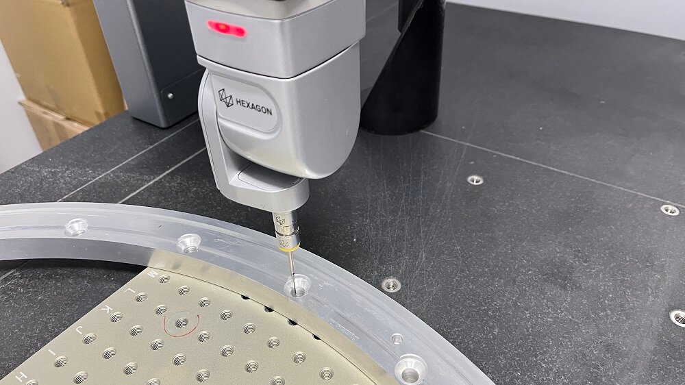
06Achieving Required Surface Quality
For typical Inconel parts (turbine components, aerospace fittings, marine hardware):
Ra 0.8–1.6 µm is standard with proper finish parameters.
Use wiper inserts for turning to improve surface finish without lowering feed.
For milling – Climb mill only. Conventional milling increases work hardening.
07Real-World Case: Machining Inconel 625 Manifolds
A contract manufacturer needed to produce 50 Inconel 625 manifolds with threaded holes and a 0.4 µm Ra seal surface. Initially, they followed standard steel parameters: 120 sfm, 0.002 IPT feed, and flood coolant. Result: Each tool lasted only 8 minutes, and thread taps broke in 3 of the first 5 holes.
After applying the principles above:
Reduced milling speed to 70 sfm, increased feed to 0.0035 IPT.
Switched to AlTiN-coated variable-flute end mills.
Implemented high-pressure coolant (1200 psi).
For tapping, used spiral-flute taps with 60% thread engagement (not 75%).
Outcome: Tool life increased to 55 minutes, zero tap breakage, and surface finish met spec on all parts.
08Key Takeaways & Actionable Recommendations
Core truth: You cannot machine Inconel like stainless steel or titanium. Every operation must be deliberately slowed down in speed but maintained in chip thickness.
Action steps to succeed with CNC Inconel parts:
1. Start with a test block – Run a 10-minute cutting test with your chosen parameters. Check tool wear under a microscope.
2. Document everything – Record speed, feed, depth, coolant pressure, and tool life for each batch.
3. Prioritize rigid setups – Use short tool holders, secure workholding, and avoid extended reach unless necessary.
4. Inspect early and often – Measure the first three parts for work hardening using a hardness tester (should not exceed 45 HRC from 35 HRC base).
5. Never re-cut a pass – If you must re-enter a slot or pocket, take a slightly deeper cut to remove the hardened layer.
By following these evidence-based methods, your CNC machining of Inconel parts will shift from unpredictable struggles to consistent, repeatable success. Start with conservative parameters, validate with real cuts, and incrementally optimize—Inconel rewards patience with precision.