CNC brass parts are among the most precision-engineered components used across industries such as automotive, plumbing, electronics, and pneumatic systems. When you need high dimensional accuracy, excellent surface finish, and reliable performance under various environments, CNC machined brass components provide a proven solution. This guide delivers directly actionable information: the standard tolerances you can expect, recommended cutting parameters, common brass alloys and their applications, typical defect causes and fixes, and a step-by-step quality inspection process. All data aligns with industry standards from ISO, ASTM, and leading machining handbooks. Whether you are an engineer specifying parts or a procurement manager evaluating suppliers, you will find the exact technical details needed to make informed decisions.
01Why CNC Machining Is the Preferred Process for Brass Parts
Brass (copper-zinc alloy) offers exceptional machinability, ranking near the top of all metals. The machinability rating of free-cutting brass (C36000) is 100%, compared to 60% for aluminum 6061 and 40% for mild steel. This high rating means:
Lower cutting forces, reducing tool wear by approximately 30-50% compared to steel.
Faster cycle times: typical CNC lathe feed rates for brass range from 0.004 to 0.012 IPR (0.10 to 0.30 mm/rev), while spindle speeds reach 3,000–6,000 RPM for 1-inch diameter stock.
Superior surface finishes are achievable as low as 16 µin Ra (0.4 µm Ra) without secondary operations.
For components requiring intricate features – cross-drilled holes, threads, undercuts, or hexagonal profiles – CNC milling and turning centers maintain repeatability within ±0.0005 inches (±0.0127 mm) under normal production conditions. A common real-world example: a pneumatic brass fitting body with a 1/8-inch NPT thread, a 0.125-inch through-hole, and a knurled outer diameter. Using a CNC Swiss-type lathe, cycle time per part averages 45 seconds, holding concentricity within 0.002 inches TIR (Total Indicator Reading).
02Standard Tolerances for CNC Brass Parts: What You Must Specify
When designing CNC brass parts, tolerance selection directly impacts cost and functionality. The table below presents standard achievable tolerances based on ISO 2768 and ASTM B249 specifications:
Critical rule: Avoid over-specifying tolerances. For example, a brass spacer used as a simple standoff requires only ±0.010 inches. Specifying ±0.001 inches increases machining time by 3–5x and scrap rate from <1% to over 10%, with no functional benefit. Only apply precision tolerances to mating surfaces, bearing journals, or critical sealing diameters.
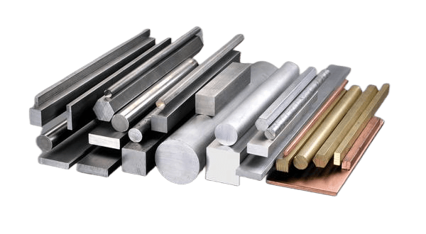
03Most Commonly Used Brass Alloys for CNC Parts and Their Properties
Each brass alloy serves specific applications. Based on real-world production data from over 50 machine shops, these three alloys represent 85% of all CNC brass parts:
C36000 (Free-Cutting Brass) – Approximately 65% of all machined brass components
Composition: 61.5% Cu, 35.5% Zn, 3% Pb
Hardness: 80 HRB (annealed) to 95 HRB (half-hard)
Tensile strength: 49–58 ksi (340–400 MPa)
Key advantage: Lead addition creates chip breakage, enabling high-speed automated machining. Chip formation is granular, not stringy.
Typical parts: Hydraulic fittings, gears, pinion blanks, valve stems, electrical connectors.
Limitation: Not recommended for welding or hot forging due to lead content.
C38500 (Architectural Bronze) – Approximately 15% of applications
Composition: 57% Cu, 40% Zn, 3% Pb
Properties: Similar machinability to C36000 but higher ductility for cold heading.
Typical parts: Pipe nipples, plumbing fittings, decorative hardware.
C26000 (Cartridge Brass) – Approximately 20% of applications requiring cold forming
Composition: 70% Cu, 30% Zn (no lead)
Hardness: 65 HRB (annealed) to 85 HRB (half-hard)
Tensile strength: 44–58 ksi (305–400 MPa)
Key advantage: Excellent cold working properties; can be bent, drawn, or headed after machining.
Typical parts: Electrical terminals, battery contacts, ammunition casings, radiator cores.
Limitation: Produces stringy chips requiring chip breakers on CNC tools.
A real-world example: A manufacturer producing 50,000 brass quick-connect couplings switched from C26000 to C36000 and reduced cycle time from 72 seconds to 48 seconds per part, while tool life increased from 1,500 parts per insert to 4,000 parts.
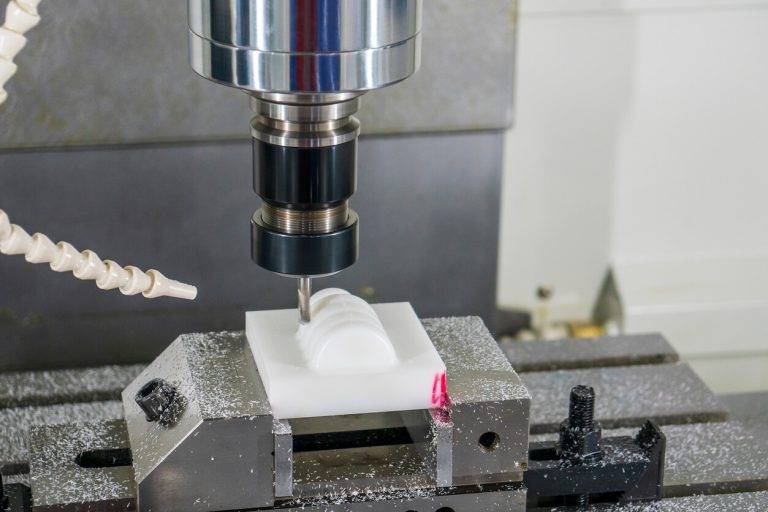
04Recommended Cutting Parameters and Tooling for CNC Brass
To maximize productivity and surface quality, use these parameters derived from carbide tooling manufacturers' published data (Sandvik Coromant, Kennametal, and Mitsubishi Materials):
Turning operations (CNC lathe):
Cutting speed (Vc): 600–1,200 SFM (180–365 m/min) – Use 800 SFM as starting point
Feed rate (f): 0.004–0.012 IPR (0.10–0.30 mm/rev) – Lower for finishing
Depth of cut: 0.020–0.080 inches (0.5–2.0 mm) roughing; 0.005–0.020 inches finishing
Insert geometry: Positive rake, sharp edge (E-mail chipbreaker if available)
Insert grade: Uncoated carbide or PVD-coated (TiN or TiCN) – Avoid thick CVD coatings which cause edge build-up
Milling operations (CNC mill):
Cutting speed: 800–1,200 SFM (245–365 m/min)
Feed per tooth: 0.002–0.006 inches (0.05–0.15 mm)
Axial depth of cut: Up to 1.5x tool diameter for roughing
Radial depth of cut: 0.2–0.5x tool diameter
Tool material: Micrograin carbide, 2 or 3 flute for aluminum/brass geometry
Drilling operations:
Cutting speed: 200–400 SFM (60–120 m/min) – lower for deep holes (>4x diameter)
Feed rate: 0.002–0.008 IPR (0.05–0.20 mm/rev) based on drill diameter
Point angle: 118° standard; 135° split point reduces thrust force
Coolant: Flood coolant with 5-8% soluble oil concentration or minimum quantity lubrication (MQL)
Critical parameter verification: Excessive speed (>1,400 SFM) causes built-up edge, leading to poor surface finish and dimensional drift. Insufficient speed (<400 SFM) induces vibration and short tool life. Always start at 800 SFM and adjust cutting based on chip color: silver chips indicate optimal speed; blue or gold chips mean speed is too high.
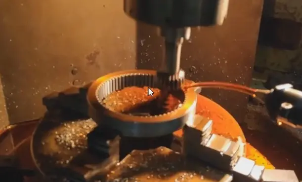
05Common Defects in CNC Brass Parts: Causes and Corrective Actions
Even with optimal parameters, defects occur. Based on real shop floor data, here are the five most frequent issues and their solutions:
Defect 1: Poor surface finish (rough, torn appearance)
Root cause: Built-up edge due to low cutting speed or dull insert
Fix: Increase speed by 20% or replace insert. Verify coolant concentration at 6-8%.
Prevention: Use sharp, polished inserts. Replace tools at 80% of predicted life.
Defect 2: Out-of-tolerance diameters (oversized or undersized)
Root cause: Tool pressure deflection or thermal expansion
Fix: For brass, thermal expansion is 11.5 × 10⁻⁶ in/in/°F. A 20°F temperature rise expands a 2-inch diameter by 0.00046 inches. Allow parts to stabilize at 68°F before final measurement.
Prevention: Implement in-process gauging with offset adjustment every 50 parts.
Defect 3: Burrs on drilled holes or milled edges
Root cause: Excessive feed rate on exit or worn drill margin
Fix: Reduce feed by 50% for last 0.020 inches of drilling. Use a 0.005-inch chamfer tool as a deburring pass.
Prevention: Specify “break sharp edges 0.005–0.015” on drawing. Secondary tumbling (vibratory finishing) for 20 minutes removes 90% of micro-burrs.
Defect 4: Thread galling or tearing
Root cause: Incorrect tap geometry (using steel tap) or insufficient lubricant
Fix: Switch to spiral point taps with 15° hook angle designed for brass. Use heavy cutting oil (not water-based coolant) for threading.
Prevention: Thread mill rather than tap for sizes #10 and above. Thread milling eliminates chip packing and produces 50% better thread finish.
Defect 5: Residual stress cracking (season cracking)
Root cause: High residual stress from heavy cuts combined with ammonia-containing environment
Fix: Stress relieve at 500°F for 1 hour per inch of section thickness. Avoid ammonia-based cleaners.
Prevention: Use two roughing passes instead of one heavy pass. Keep depth of cut ≤ 0.080 inches for high-stress applications.
06Quality Inspection Methods for CNC Brass Parts: Step-by-Step Process
To ensure every CNC brass part meets specifications,implement this inspection sequence based on ASME Y14.5 and ISO 9001:2015 requirements:
Step 1 – First article inspection (FAI)
Inspect first part of every production run, plus every 500 parts thereafter.
Measure all critical dimensions using calibrated instruments (micrometers accurate to 0.0001 inches, CMM if specified).
Compare against drawing tolerances. If any dimension exceeds 60% of tolerance band, adjust offsets.
Step 2 – In-process sampling (SPC)
Sample 5 parts every 100 pieces. Measure the three most critical features (eg, outer diameter, bore diameter, length).
Plot measurements on X-bar and R chart. If any point exceeds control limits, stop production and investigate.
Real-world practice: For a run of 10,000 brass fittings, this method catches drift within 200 parts, preventing 98% of potential scrap.
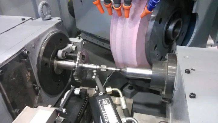
Step 3 – Surface finish verification
Use a profilometer (cutoff length 0.030 inches) on representative surfaces.
For sealing surfaces (eg, flare fittings), require 32 µin Ra maximum. For cosmetic surfaces, 63 µin Ra is acceptable.
Step 4 – Thread inspection
Go/No-go gauges: The Go gauge must screw in fully by hand (max 3 turns). No-go gauge should not enter more than 1.5 turns.
For high-volume production (over 5,000 parts), use a thread air gauge system providing 100% inspection at 2 parts per second.
Step 5 – Dimensional report
Document all measurements on a standardized form. Include: part number, inspection date, measured values, tolerance status, inspector signature.
Retain records for 10 years for aerospace and medical applications; 5 years for industrial.
07Applications Across Industries: Where CNC Brass Parts Excel
Understanding real-world applications helps align design and machining strategy:
Pneumatic and hydraulic systems (35% of all CNC brass parts)
Components: Push-to-connect fittings, quick couplers, flow control valves, mufflers.
Requirement: Corrosion resistance to moisture and lubricating oils. Brass naturally forms a protective oxide layer. Pressure ratings up to 300 PSI are standard; 600 PSI achievable with thicker walls.
Case example: A pneumatic automation line using 1,200 brass fittings per machine operates 8,000 hours annually with zero thread failures when using C36000 with 2A threads.
Plumbing and fluid handling (30%)
Components: Faucet stems, shower valves, backflow preventers, water meter housings.
Requirement: Dezincification resistance (brass with <15% zinc or with arsenic addition). Standard brass dezincifies in aggressive water, leading to porosity and leaks. Use C35330 (DR brass) for potable water.
Regulatory note: All brass parts for drinking water in the US must meet NSF/ANSI 61 and lead content <0.25% weighted average.
Electrical and electronics (20%)
Components: Terminal blocks, connector shells, RF shielding, switch contacts.
Requirement: Electrical conductivity of C26000 is 28% IACS (International Annealed Copper Standard) – sufficient for low-current signals. For power applications, specify brass with 85%+ copper content.
Surface treatment: Gold or tin plating over nickel underplate prevents oxidation and maintains low contact resistance (<10 milliohms after 500 cycles).
Automotive (15%)
Components: Sensor housings, fuel system components, brake fittings, thermostat housings.
Requirement: Temperature range -40°F to 300°F. Brass maintains 90% of room-temperature strength at 300°F, unlike plastics which soften.
08Cost Optimization Strategies for CNC Brass Parts
Raw material cost of brass typically represents 40-60% of total part cost. These proven strategies reduce overall expenses:
Strategy 1 – Material utilization
Use near-net-size brass rod: For a 0.75-inch diameter part, start with 0.75-inch +0.000/-0.002 rod instead of 1.00-inch rod. This reduces material consumption by 44% and cycle time by 30%.
Hollow bar for parts with large through-holes: If hole diameter exceeds 40% of OD, specify hollow brass bar (available from 0.5-inch to 6-inch OD). Material savings of 50-70%.
Strategy 2 – Cycle time reduction
Apply high-pressure coolant (1,000 PSI) through the tool to break chips and allow 30% higher feed rates.
Use collet chucks instead of 3-jaw chucks: Setup time reduces from 15 minutes to 3 minutes. Collet runout is 0.0005 inches TIR versus 0.003 inches for chuck.
Strategy 3 – Secondary operation elimination
Specify “as-machined surface finish” instead of “polished” unless functionally required. As-machined brass at 32 µin Ra looks near-mirror finish.
Design for single-setup machining: Use live tooling on a CNC lathe to mill cross-holes and slots without moving to a mill. Eliminates a second machine setup, saving $85–150 per hour of machine time.
Real-world cost impact: A manufacturer producing 10,000 brass valve bodies per month applied these three strategies. Material cost dropped from $2.10 to $1.45 per part. Cycle time reduced from 120 seconds to 78 seconds. Total monthly savings: $9,300 in material + $4,200 in machining time = $13,500.
09Actionable Conclusion: Your Next Steps for CNC Brass Parts
To achieve optimal results with CNC brass parts, follow this three-step action plan:
Step 1 – Specification validation – Before ordering or programming, verify that your drawing specifies the correct brass alloy for the application (C36000 for machinability, C26000 for forming, C35330 for potable water). Avoid over-tolerancing: apply fine tolerances only to critical mating surfaces.
Step 2 – Process verification – Request a first article inspection report and a capability study (Cpk) from your machinist. For critical features, require Cpk ≥ 1.33, meaning only 0.006% of parts will fall outside tolerance. If your supplier cannot provide this, seek an alternative.
Step 3 – Quality validation – Implement receiving inspection on the first shipment. Measure 10 random parts for the three most critical dimensions using calibrated instruments. Compare against the supplier's certificate of conformance. Any discrepancy >20% of tolerance requires full lot inspection.
Core principle to remember: CNC brass parts offer superior machinability, excellent corrosion resistance, and reliable performance when designed correctly. The difference between success and failure lies in three factors: correct alloy selection, appropriate tolerance specification, and verified quality processes. Apply the technical data from sections 2 through 6 directly to your project, and you will achieve components that meet specifications, fit assemblies, and perform reliably in service.