One type of core technology combination in modern manufacturing is CNC (Computer Numerical Control), which uses computer programs to automatically control the movement of machine tools. The other type, in terms of processing technology, is milling that uses rotating tools to remove materials. When the two are combined with each other, they will form CNC milling is known as one of the most versatile and high-precision parts manufacturing methods. This article will directly give you the answers you need most, that is, how to quickly select the correct CNC milling solution based on part requirements, materials and budget, and how to solve common problems.
01What is CNC milling? Core definitions and workflow
The essence of CNC milling is to use digital instructions to drive rotating tools, and then perform cutting and forming operations on the workpiece. Its full working path is like this:
1. Design modeling : Use CAD software to draw three-dimensional parts drawings.
2. Use CAM software to generate. The generated content is G code. The G code covers the tool path, spindle speed, feed rate and other instructions.
3. Clamping and tool setting : Fix the blank on the machine tool table and set the tool zero point.
4. During automatic processing, the CNC controller will read the code line by line, and the servo motor will then drive the spindle, allowing the spindle and worktable to move according to the predetermined trajectory, and the tool will then remove excess material.
5. Inspection completed : online measurement or three-coordinate measurement to verify dimensions.
The key advantage is that compared with traditional manual milling machines, CNC milling can continuously complete the processing of complex contours, hole systems and curved surfaces without manual intervention. Its repeated positioning accuracy can reach plus or minus 0.005mm, thus improving production efficiency by three to ten times.
02CNC milling vs. ordinary milling: core differences in five dimensions
To draw the conclusion of selection, if there is a free-form surface in the part, the number of holes is more than 5, and the tolerance is less than or equal to plus or minus 0.05 mm. Or if the annual demand is greater than 100 pieces, then CNC milling must be used.
03How to choose the correct CNC milling solution? 4-step decision-making method
Step 1: Determine the number of axes – 3, 4 or 5?
Tools that move along X/Y/Z lines can be used for 3-axis milling. This milling method is suitable for flat surfaces, vertical sides and simple cavities. It has the lowest cost and accounts for about 60% of the total demand.
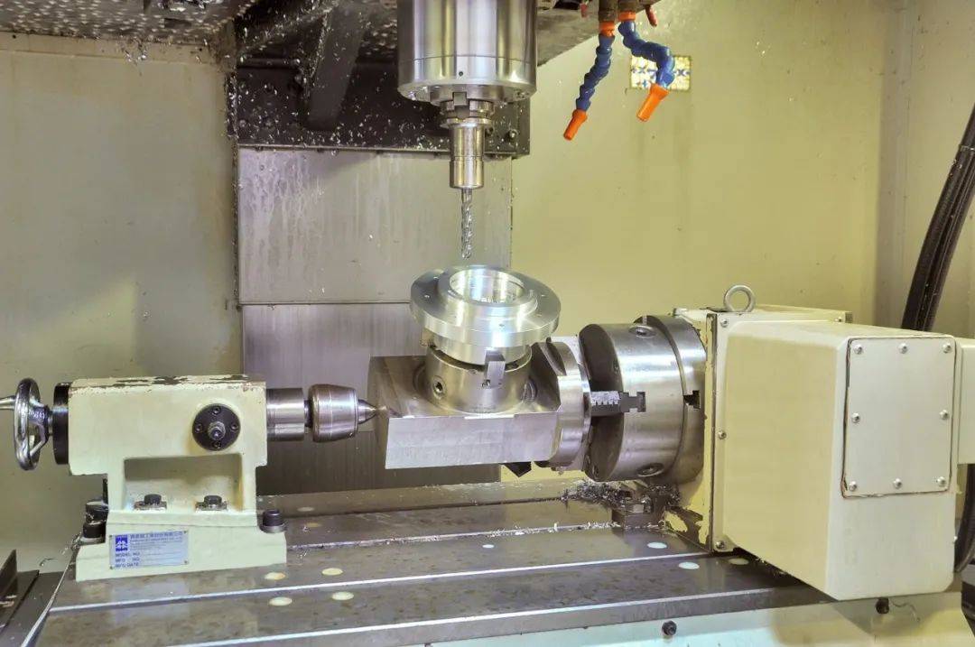
4-axis milling will add a rotation axis. This rotation axis usually rotates around the X-axis. It is suitable for processing holes on cylinders, processing spiral grooves, and processing cams.
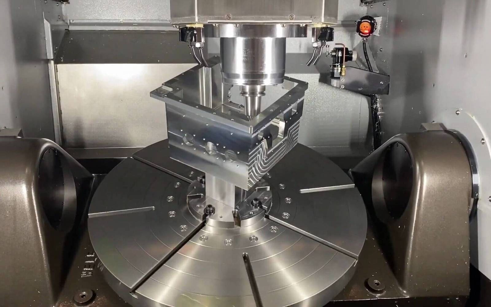
5-axis milling has two rotating axes that are linked. It can process all surfaces except the bottom surface in one clamping. It can solve problems such as deep cavity interference, undercuts and impellers. However, its equipment price is more than 4 times that of a 3-axis machine.
> Naturally integrated into keywords: processing precision control
No matter how many axes are selected, the final control of machining accuracy relies on three major hardware, namely ball screw gap compensation, spindle thermal deformation suppression, and servo motor closed-loop feedback. If any one of these items is missing, the nominal 0.005mm accuracy cannot be achieved.
Step 2: Select cutting parameters according to material (common cases)
Regarding aluminum alloy 6061, the spindle speed is in the range of 8000 to 12000rpm, the feed rate is in the range of 1500 to 2500mm/min, and a 2-edge aluminum milling cutter is used.
304 stainless steel, the rotation speed should be between 2000 rpm and 3500 rpm, the feed speed should be 300 mm per minute to 600 mm per minute, the tool is a 4-edge coated tool, and coolant must be used.
When used for engineering plastic POM, the required speed range is 6000-8000rpm. Furthermore, the feed speed is set at 1200-1800mm/min. In addition, a single-edged milling cutter is used to avoid melting.
The case shows that there is an electronics factory that batch-processes aluminum alloy radiators. At the beginning, the work was carried out based on the parameters of the steel parts. The specific rotation speed was 3000rpm. Such operations caused the tools to stick to chips and the surface became rough. Then, the rotation speed was adjusted to 10,000 rpm. After that, the surface roughness was reduced from Ra3.2 to Ra0.8, and at the same time, the tool life was increased from 200 pieces to 800 pieces.
Step 3: Determine the clamping solution – pressure plate or jig?
Pressing plate : suitable for single pieces or small batches of rough materials, but it occupies the processing area and can only process the top surface.
Pneumatic or hydraulic fixtures, when the batch size is greater than or equal to 50 pieces, the cost will be diluted, and multiple workpieces can be clamped at one time to achieve "unattended" processing.
Step 4: Acceptance Criteria – What key indicators must be tested?
Positioning accuracy, measured by laser interferometer, follows the standard ISO 230-2. For vertical machining centers, the usual requirement is ±0.005mm/full stroke.
Repeatable positioning accuracy : ballbar test, requirement ≤±0.003mm.
In order to cut sample parts for trial, we need to carry out processing work according to the drawings provided by the customer, then use three-dimensional coordinates to measure all dimensions, and finally issue a test report.
04Quick diagnosis of common problems in CNC milling (Q/A format)
Q1: What should I do if there are obvious vibration marks on the CNC milling surface?
First, reduce the spindle speed or increase the feed rate. The cause of vibration marks is mostly caused by the overhang of the tool being too long, or the cutting parameters causing resonance, and the clamping length of the tool needs to be shortened to within four times the diameter.
Q2: What is the reason why milling cutters frequently chip and break?
The first is to immediately check whether the spindle runout exceeds 0.01mm. The second is to confirm whether the feed per tooth exceeds the recommended value of the tool. The main cause of edge chipping is mechanical clearance or overload.
Q3: The root cannot be cleared when processing an inner right angle. How to solve the problem?
Even the smallest diameter milling cutter still has an arc radius. The correct approach is to use electric discharge machining to clean the root, or add a 0.2mm process fillet to the design end.
Q4: There are burrs and flanges on the surface of aluminum alloy after processing. How to eliminate them?
A: Converting uphill milling to down milling can reduce burrs. At the same time, the final finishing allowance can be reduced to 0.05mm, and a new sharp blade can be used.
Q5: Can three-axis CNC process parts with negative angles?
A: It is not possible to process directly. You have to use a T-shaped knife, or an angle head attachment, or tilt the workpiece to clamp it to simulate four axes. Otherwise, you need to upgrade to a 4/5-axis machine tool.
Q6: How to judge whether to choose high-speed machining or heavy cutting?
A: For small-diameter tools, that is, tools with a diameter of less than or equal to 6 mm, high-speed processing should be selected, that is, a processing method with a rotation speed of more than 15,000 rpm. For rough machining with large allowances, heavy cutting should be selected, that is, the cutting method with low speed and large depth of cut.
05Deduce your correct choice from typical scenarios
Scenario 1: Regarding the single-piece production in the maintenance workshop, what you need is a lathe-type milling machine with manual/CNC functions. The priority is a 3-axis vertical milling machine that does not require a tool magazine and can be programmed manually. You must choose a domestically produced economical one within the budget. The key is to ensure that the spindle taper is above BT30.
Scenario 2: There is a mass production of precision parts (the specific output is 5,000 pieces per year, the tolerance range is ±0.01mm). There is such a requirement, that is, a machining center with a tool magazine of more than 24 tools must be selected, and a fourth-axis pre-installed interface must be configured. At the same time, the supplier is required to provide the static accuracy test report of the ballbar and the first full-size test results.
Scenario 3 – The prototype prototype can be quickly iterated. It does not require industrial-grade CNC, but uses a desktop-grade CNC milling machine. The working stroke of this milling machine only needs to reach 300×200×150mm, and it is made with plastic or wood substitute materials. Its single-piece cost is lower than outsourcing 3D printing.
> Naturally integrated into keywords: tool path optimization
In the above-mentioned mass production scenario, tool path optimization can shorten the machining time by more than 30%. The specific method adopted is to use trochoidal milling to replace linear feed to reduce the load, maintain a constant chip thickness through a dynamic milling strategy, and separately program the rapid traverse speed (G00) and cutting feed (G01).
06Repeat core ideas and final action suggestions
The core conclusion is reiterated :
In terms of relationship, CNC and milling are like this. It is the synergy between the "control brain" and the "execution limbs". As far as CNC milling is concerned, it has replaced manual processing and has become the first choice in terms of accuracy and efficiency.
There are four main steps in selecting the number of axes of the model, parameters, parts related to clamping, and acceptance. Any step among them is indispensable. If any one of them is ignored, the cost will be out of control or the quality will fail.
Common vibration mark problems, as well as edge chipping and burr conditions, all have clear and clear solutions. Quick reference based on Q/A can quickly achieve positioning.
Action recommendations (directly executable) :
1. Determine the requirements boundaries that need to be understood: draw drawings containing workpieces, mark the tightest tolerances, indicate the most complex and intricate features, and estimate the expected annual production quantity.
2. In terms of calculating the cost of a single piece, the hourly rate of CNC equipment is approximately within the range of 60 to 150 yuan. This includes the cost of tool electricity and labor, and it must be compared with the price generated by outsourcing.
3. Start the trial cutting verification step: Whether you choose your own purchasing method or choose an external cooperation channel, you must first process one to three sample parts, and then measure all important dimensions.
4. Build a tool list and prepare two to three specifications of high-quality milling cutters for commonly used materials. For example, use a three-edged milling cutter for aluminum and a four-edged cobalt-containing milling cutter for steel to avoid frequent tool changes.
Follow the above guide and you will select the most suitable CNC milling solution within 24 hours and reduce the common failure rate by more than 70%. If there is a specific issue that is not covered, check ISO 10791 (the standard for testing machining centers), or refer to the cutting data book given by the machine tool manufacturer.


