Quick answer:
G02 is the CNC G-code command for clockwise circular interpolation. It moves the tool along a circular arc in a clockwise direction when viewed from the tool’s perspective. G02 requires either an R value or I/J coordinates to define the arc, along with the endpoint coordinates. It is one of the most commonly used commands in CNC machining, alongside G01 for linear moves and G03 for counterclockwise arcs. Understanding how G02 works is essential for anyone programming mills, lathes, or machining centers.
If you are new to CNC programming or you have been using conversational software, G02 can feel confusing at first. The good news is that once you understand a few key rules, it becomes straightforward. This guide explains how G02 works, how to write it correctly, what the I, J, and R values mean, and what mistakes to avoid.
YPMFG works with CNC machining every day, and we see the same G-code errors on customer drawings and programs. This article is written from that practical perspective, so you can apply it directly to your own parts.
Table of Contents
1. What Is G02 in CNC?
2. G02 vs G03: The Difference
3. How to Write a G02 Command
4. Understanding I, J, and R Values
5. G02 on Mills vs Lathes
6. Common G02 Mistakes and How to Avoid Them
7. G02 and Tool Path Verification
8. Practical Questions About G02 Code in CNC
9. Getting Your CNC Programs Reviewed
What Is G02 in CNC?
G02 is the G-code command for clockwise circular interpolation. When the machine receives a G02 command, it moves the tool along an arc from the current position to a specified endpoint. The arc direction is clockwise when viewed from the positive Z-axis looking down toward the workpiece.
The command is used in both milling and turning operations. On a mill, G02 creates arcs in the X-Y plane by default. On a lathe, it works in the X-Z plane. The plane can be changed using G17, G18, or G19, but G17 is the default for most milling work.
G02 is not a single-line instruction. It always needs supporting data, including the endpoint coordinates and either a radius value or incremental center coordinates. Without these, the control cannot calculate the arc path.
G02 vs G03: The Difference
The difference between G02 and G03 is simply the direction of the arc.
The direction is always determined by viewing the arc from the positive axis of the active plane. For a standard mill setup using G17, you look from the positive Z direction down onto the X-Y plane.
A common beginner mistake is assuming that G02 always means “outside” and G03 always means “inside.” That is not correct. The direction depends entirely on the tool path and the plane you are working in.
If you are programming a contour that changes direction, you may need both G02 and G03 in the same operation. For example, a rounded slot may use G02 at one end and G03 at the other.
How to Write a G02 Command
A basic G02 command on a mill looks like this:
G02 X... Y... R... F...
Or with I and J values:
G02 X... Y... I... J... F...
The X and Y values define the endpoint of the arc. The R value defines the radius. The I and J values define the distance from the start point to the arc center. The F value sets the feed rate.
Here is a simple example:
G02 X60 Y40 R20 F200
This command moves the tool in a clockwise arc from its current position to X60, Y40, with a radius of 20 mm, at a feed rate of 200 mm/min.
The R method is easier to write, but it has limitations. If the arc is greater than 180 degrees, the control may not know which arc you want. In that case, you should use a negative R value or switch to I and J.
Understanding I, J, and R Values
The R value is the simplest way to define an arc. You tell the machine the radius,and it calculates the center automatically. However, the R method cannot define a full circle. For a full circle, you must use I and J.
I and J define the arc center relative to the start point. I is the distance from the start point to the center along the X-axis. J is the distance along the Y-axis. On a lathe, you would use I and K instead.
For example, if your tool starts at X20, Y10 and the arc center is at X20, Y30, the J value would be 20.
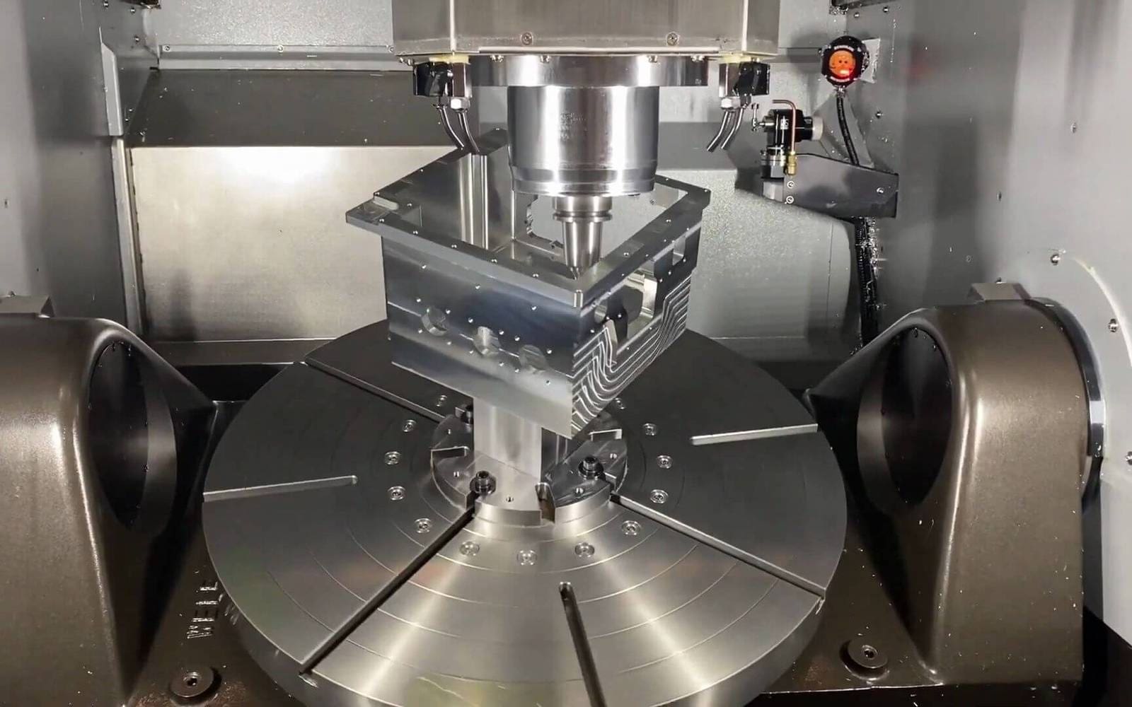
Many CAM systems output I and J automatically. If you are writing code by hand, you need to calculate the center coordinates carefully. A small error in I or J can produce a wrong arc or an alarm on the machine.
G02 on Mills vs Lathes
On a milling machine, G02 is used in the X-Y plane by default. It is common in contouring, pocketing, and radius generation. On a lathe, G02 is used in the X-Z plane, and the arc center is defined with I and K instead of I and J.
The direction of the arc can appear reversed on a lathe because the tool position and axis orientation are different. Always check the machine’s axis conventions before writing G02 code.
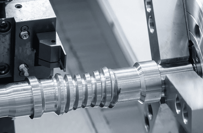
For CNC turning operations, G02 is often used to create fillets, chamfers, and curved profiles. The same G02 command works, but the coordinate system and plane settings are different.
If you are programming both mills and lathes, it is worth keeping a reference sheet for each machine type. The logic is the same, but the axis names and plane defaults are not.
Common G02 Mistakes and How to Avoid Them
Several mistakes come up repeatedly in CNC programs. Here are the most common ones and how to avoid them.
One of the most dangerous mistakes is using the wrong arc direction on a finishing pass. The tool may cut air or, worse, cut into the part. Always simulate the tool path before running the program on the machine.
YPMFG recommends verifying every G02 and G03 block in your CAM simulation software before sending the program to the shop floor. This step catches most arc-related errors before they cost you material and machine time.
G02 and Tool Path Verification
Tool path verification is not optional when you are using circular interpolation. A single incorrect I or J value can produce a tool path that looks correct on paper but fails on the machine.
Most modern CAM systems include simulation tools that show the exact tool path. Use these tools to check the arc direction, the radius, and the endpoint of every G02 block. If you are writing code manually, consider using a backplotter or a simple G-code viewer.
Verification is especially important for precision CNC machining, where a small arc error can affect the fit of a mating part. A radius that is off by 0.1 mm may be acceptable for some applications, but not for others.
If you are unsure about a G02 block, it is better to ask for an engineering review than to run the program and risk scrapping a part.
Practical Questions About G02 Code in CNC
Can G02 be used to cut a full circle?
Yes, but only if you use I and J values. The R method cannot define a full circle because the control cannot determine which of the two possible arcs you mean. With I and J, you define the center point, and the machine can complete a full 360-degree arc.
What is the difference between G02 and G03?
G02 is clockwise circular interpolation, and G03 is counterclockwise. The direction is determined by viewing the arc from the positive axis of the active plane. On a standard mill with G17 active, you view from the positive Z direction.
Do I need to use G02 for every arc?
No. Many CAM systems output arcs using G02 or G03 automatically. Some programmers prefer to break arcs into small linear moves, but this increases program size and can reduce surface finish quality. G02 is the standard and preferred method for circular moves.
What happens if I use a negative R value?
A negative R value tells the control to use the larger arc between two points. This is useful when the arc is greater than 180 degrees. However, not all controls handle negative R values the same way, so check your machine manual before using it.
Is G02 the same on all CNC machines?
The basic logic is the same, but the axis names and plane defaults can vary. Lathes use I and K instead of I and J. Some controls also support additional parameters. Always verify the format for your specific machine control.
Why does my machine alarm out on a G02 command?
The most common causes are a missing endpoint, an incorrect R value, or an I/J calculation error. The control cannot calculate the arc if the data is incomplete or inconsistent. Check the block against the drawing and verify the start point.
Getting Your CNC Programs Reviewed
G02 is a simple command, but the errors around it are not always obvious. If you are writing G-code by hand, or if you are converting a program from one machine to another, a second review can save you time and material.
YPMFG provides CNC machining services and engineering support for customers who need help with program review, tool path verification, and custom CNC solutions. If you have a part drawing or an existing program that you are not confident about, you can send your specifications to YPMFG for an engineering assessment.
We can review your G-code, check the arc definitions, and help you confirm that the program will run correctly on your machine. This is especially useful for complex parts where a single arc error can ruin the final product.
Making the Right Call on G02 Programming
G02 code in CNC is not difficult once you understand the rules. The key points are simple: know your plane, use the correct direction, and verify your R or I/J values before running the program.
The cost of an arc error is not just the scrap part. It is also the machine downtime, the rework time, and the delay in your delivery schedule. Taking a few extra minutes to verify your G02 blocks can prevent all of that.
If you are working on a new part and want to be sure your program is correct, send your drawing and program to YPMFG. Our engineers can review the tool path, confirm the CNC programming details, and give you a clear answer before you commit to cutting metal.