Quick answer:
CNC programming codes are the standardized instructions that control machine tools, primarily using G-code for geometry and movement. These codes tell the CNC machine where to move, how fast to cut, and when to change tools. Understanding these codes is essential for optimizing machining efficiency and ensuring part accuracy.
Manufacturers rely on these instructions to translate CAD designs into physical components. Without correct coding, even the most advanced machinery cannot produce precise parts. This guide explains the core functions of G-codes and M-codes for engineering teams.
YPMFG supports complex manufacturing projects by providing precise CNC machining services. Our engineering team ensures that your design specifications are accurately interpreted into executable code. We help clients avoid common programming errors that lead to costly material waste.
Core Functions of G-Code and M-Code
CNC machines operate using two primary types of instructional codes. Each type serves a distinct purpose in the machining process. Understanding this distinction is critical for effective production planning.
G-code, or geometric code, controls the machine’s physical movements. It defines tool paths, feed rates,and positioning coordinates. This code determines the shape and dimensions of the final part.
M-code, or miscellaneous function code, handles auxiliary machine operations. It controls actions like spindle rotation, coolant flow, and tool changes. These functions support the main cutting process but do not move the tool.
Both codes must work in synchronization to ensure smooth operation. Errors in either code can cause machine collisions or poor surface finishes. Precision in coding directly impacts the quality of CNC machining services.
Essential G-Codes for Machining Operations
Certain G-codes are fundamental to almost every machining program. These commands establish the baseline for tool movement and coordinate systems. Mastery of these codes is necessary for any CNC programmer.
G00 represents rapid positioning. It moves the tool at maximum speed to a target location. This movement does not cut material and should be used carefully.
G01 indicates linear interpolation. The tool moves in a straight line at a specified feed rate. This code is used for straight cuts and milling operations.
G02 and G03 control circular interpolation. G02 moves the tool clockwise, while G03 moves it counter-clockwise. These codes are essential for creating arcs and circular features.
G17, G18, and G19 select the working plane. They determine which axis plane the circular motions occur in. Correct plane selection prevents calculation errors in tool paths.
Using the wrong G-code can lead to unintended tool paths. Always verify the active plane and motion type before running a program.
Critical M-Codes for Machine Control
M-codes manage the peripheral functions that support the cutting process. These codes ensure the machine environment is suitable for machining. Improper use can damage tools or compromise safety.
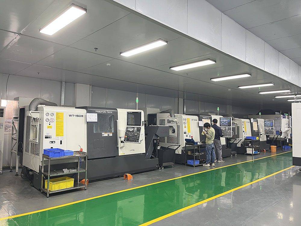
M03 and M04 start the spindle rotation. M03 rotates the spindle clockwise, while M04 rotates it counter-clockwise. The direction depends on the tool type and material being cut.
M05 stops the spindle rotation. This command is used after a cutting operation is complete. It prevents unnecessary wear on the spindle bearings.
M08 and M09 control the coolant system. M08 turns the coolant on to reduce heat and friction. M09 turns the coolant off, typically before retracting the tool.
M06 initiates an automatic tool change. The machine retrieves the next tool from the magazine and loads it. This code is vital for multi-operation programs.
Incorrect M-code usage can cause tool breakage or overheating. Ensure coolant and spindle commands align with material requirements.
Programming Standards and Coordinate Systems
CNC programs rely on strict adherence to coordinate system standards. The most common standard is ISO, which defines how axes are oriented. Some regions use Fanuc standards, which are similar but have minor differences.
Absolute programming (G90) defines positions relative to a fixed origin. Incremental programming (G91) defines positions relative to the last point. Choosing the right mode affects how complex paths are calculated.
Tool length compensation (G43/G44) adjusts for varying tool lengths. This feature allows the same program to run multiple tools accurately. It eliminates the need to recalculate Z-axis depths manually.
Workpiece coordinate systems (G54-G59) define the part’s origin on the machine bed. This allows operators to set up multiple parts without changing the program. It significantly reduces setup time for batch production.
Common Errors in CNC Programming
Even experienced programmers make mistakes that affect production quality. Recognizing these errors early can save time and materials. Many issues stem from misinterpretation of code functions.
One frequent error is incorrect feed rate calculation. Setting feeds too high can break tools or damage the machine. Setting them too low reduces efficiency and increases cycle time.
Another common mistake is ignoring tool radius compensation. Failing to account for tool diameter leads to undersized or oversized parts. This error is particularly critical in precision CNC component manufacturing.
Collision avoidance is often overlooked in complex 5-axis programs. Simulating the tool path before execution helps identify potential crashes. YPMFG recommends simulation checks for all new programs.
Coolant application timing can also cause problems. Turning coolant on during rapid moves can splash lubricant and create hazards. Proper sequencing of M-codes prevents such safety risks.
Material-Specific Coding Considerations
Different materials require specific adjustments in the CNC program. Steel, aluminum, and titanium each have unique machining characteristics. The code must reflect these material properties for optimal results.
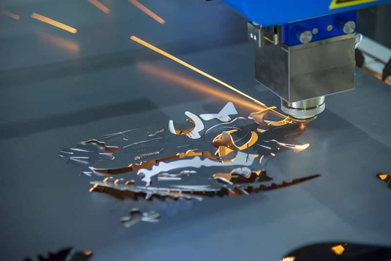
Aluminum allows for higher feed rates and speeds. It generates less heat and is easier to cut. However, it can stick to tools if not properly cooled.
Titanium requires lower speeds and steady feed rates. It has poor thermal conductivity, leading to heat buildup. Aggressive cutting can cause tool wear and part distortion.
Stainless steel needs consistent cutting parameters to prevent work hardening. Intermittent cuts or varying speeds can degrade surface finish. Stable programming ensures uniform material removal.
Choosing the right parameters for the material is crucial. Incorrect settings can ruin expensive raw materials and tools.
Optimizing Code for Efficiency and Quality
Efficient programming reduces cycle times and improves part consistency. Small adjustments in code structure can yield significant benefits. Focus on minimizing non-cutting movements and optimizing tool paths.
Shorten rapid travel distances between cutting operations. Excessive movement wastes time and increases wear on machine axes. Direct paths between points are usually the most efficient.
Use canned cycles for repetitive features like drilling or tapping. These cycles automate complex sequences, reducing program length. They also ensure consistency across multiple identical holes.
Optimize tool entry and exit strategies. Plunging into material can cause tool breakage. Using helical interpolation or ramping provides safer entry methods.
Regularly review and update legacy programs. Older codes may not utilize modern machine capabilities. Upgrading programs can enhance performance and precision.
Verification and Testing Procedures
Before running a program on the production floor, verification is essential. Digital simulation allows engineers to check for errors safely. This step prevents costly machine damage and material loss.
Simulate the entire machining process using CAM software. Check for collisions, over-travel, and incorrect tool paths. Verify that all G-codes and M-codes execute as intended.
Dry runs without material provide another layer of safety. Observe the machine’s movements to confirm accuracy. Listen for unusual sounds that indicate potential issues.
First-article inspection validates the program’s output. Measure key dimensions against the design specifications. Adjust offsets or code parameters if deviations are found.
Thorough testing ensures reliable production outcomes. Skipping verification steps increases the risk of failure.
Technical Documentation and Support
Proper documentation supports ongoing maintenance and troubleshooting. Clear comments within the code explain complex logic. This practice assists other engineers who may modify the program later.
Maintain a library of verified macro programs. Reusable code segments improve consistency across projects. They reduce the time needed to write new programs from scratch.
Keep records of successful cutting parameters for different materials. This data helps in selecting initial settings for new jobs. It serves as a reference for future engineering evaluations.
YPMFG provides comprehensive technical support for programming challenges. Our team can review your code for optimization opportunities. We offer engineering assessments to improve your manufacturing workflow.
Practical Questions Before Choosing a CNC Strategy
Engineers often have specific questions about code implementation. Addressing these concerns helps in making informed decisions. Here are answers to common practical inquiries.
What is the difference between G-code and M-code?
G-code controls tool movement and geometry, while M-code manages machine functions like spindle and coolant. Both are required for complete machine operation. G-code handles the cutting path, whereas M-code handles auxiliary support tasks.
Why do my parts have dimensional errors?
Dimensional errors often stem from incorrect tool compensation or worn tools. Verify your CNC machining parameters and check tool wear regularly. Programmatic errors in coordinate systems can also cause misalignment issues.
How can I reduce cycle time in my program?
Minimize rapid travel distance and use efficient canned cycles. Optimize feed rates based on material properties. Consult with experts like YPMFG to analyze your current code for inefficiencies.
Is it safe to run unverified code on production machines?
No, running unverified code poses significant safety risks. Always simulate the program first to detect collisions. Dry runs help confirm machine behavior before full production begins.
Choosing the Right CNC Programming Approach
Effective CNC programming requires a balance of theory and practice. Understanding the nuances of G-codes and M-codes is just the beginning. Successful implementation depends on careful planning and verification.
Collaborating with experienced manufacturers ensures your code is optimized. Professional teams can identify potential issues before they impact production. This partnership leads to higher quality and lower costs.
YPMFG specializes in delivering high-precision CNC parts manufacturing services. We assist clients in refining their programming strategies for better results. Our goal is to streamline your manufacturing process through expert guidance.
Contact our engineering team to discuss your project requirements. Send your specifications for a detailed technical evaluation. We recommend starting with a sample test to validate your approach.