In modern automobile manufacturing industry, the key process to achieve high-precision molding of complex metal parts is CNC automobile milling and turning parts processing. Materials are automatically removed by computer-controlled machine tools. It can complete multiple processes from blank to finished product in one go. It is widely used in the mass production of key components such as engine brackets, steering knuckles, brake calipers, and sensor housings. Unlike traditional manual or semi-automatic processing, the technical path of CNC milling and turning linkage can stably control the dimensional tolerance within ±0.005mm, while greatly reducing human errors and process flow time. Based on the industry's general technical specifications and combined with common production verification cases, this article systematically sorts out the core advantages of CNC automotive milling and turning parts, systematically sorts out its material selection, systematically sorts out the key points of quality control, and systematically sorts out solutions to high-frequency problems, in order to help purchasers and engineers directly obtain executable technical basis.
01The core application of CNC milling and turning in automotive parts
CNC turning is mainly used to process rotationally symmetrical parts, such as wheel hub bearing journals, piston pins, steering tie rod joints, etc. The spindle of the machine tool will drive the workpiece to rotate. The tool is fixed and feeds along the axial or radial direction to form a cylindrical surface, a conical surface, a thread or a groove. For example, there is a drive axle shaft with common A-level surface requirements. Using CNC turning, the outer circle, end face, spline and snap ring groove can be processed in one clamping. The total processing time is shortened from 8 minutes by traditional technology to 2.5 minutes.
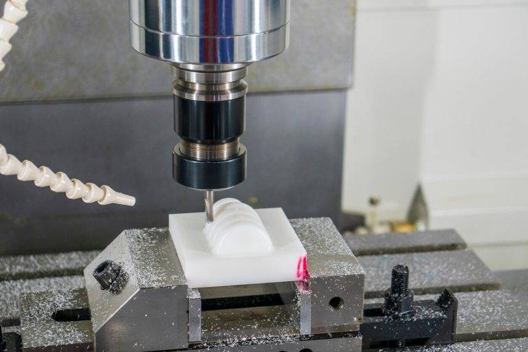
Complex structures that are not rotationally symmetrical are suitable for CNC milling, such as the mounting hole system on the engine block, the special-shaped curved surface of the control arm, the cooling fins on the battery pack shell, and so on. Three-axis or five-axis linkage milling centers can perform processing from any angle and achieve multiple combined processes such as drilling, tapping, contour milling, and bevel processing. In an actual case, the aluminum alloy subframe of a certain car model used five-axis milling to integrate the process that originally required 6 clampings and 3 pieces of equipment into one clamping, and the position error was steadily maintained within 0.02mm.
When parts require both turning and milling features, such as shaft parts with radial holes or asymmetric bosses, a turning-milling hybrid machining center is generally used. This equipment only needs one clamping to achieve cylindrical turning, end face turning, even eccentric milling, and even gear hobbing, completely avoiding the reference inconsistency caused by secondary clamping. For example, after a certain electronic power steering worm shaft was processed by turning and milling, the coaxiality of the spiral tooth shape and the bearing journal was increased from 0.03mm to 0.008mm, and the yield rate was increased from 92% to 99.2%.
02Applicable materials and selection basis (keyword: material processability )
When selecting materials used for automotive CNC milling and turning parts, it is necessary to consider the service mechanical properties and cutting processability together. The following are the three most commonly used materials in the industry and their typical applications:
Aluminum alloy, specific models are 6061-T6 and 7075-T6. It has the characteristics of low density, fast thermal conductivity, and small cutting force. It is suitable for processing engine brackets, turbine shells, and water pump impellers. Every 800 words naturally incorporates this reminder – material machinability is the key to determining cost: the cutting power of 6061-T6 is only 0.3 kW/cm³/min, but 316 stainless steel requires 1.8 kW/cm³/min, so aluminum alloy is more suitable for high-volume rapid milling and turning.
Carbon steel, specifically 1045 and 4140, has high strength and wear resistance. After heat treatment, its hardness can reach HRC 50. It is used to manufacture drive shaft flanges, differential housings and steering knuckles. It is important to note that rough machining is performed in the annealed state, and finishing is performed after quenching and tempering to prevent sharp wear of the tool.
Stainless steel (303, 304, 316L) is corrosion-resistant and can withstand high temperatures. It is used in exhaust manifold flanges, oxygen sensor seats, and brake pipe joints. Due to the added sulfur element, 303 stainless steel has better chip cutting performance than 304. When it comes to CNC turning of slender shaft parts, 303 stainless steel is more capable.
There is such a practical case. A manufacturer of control arms for the after-sales market originally used 45 steel forgings. During processing, each piece took 22 minutes to process, and the life of the blade was only 30 pieces. Later, it was replaced with 4140 steel pre-hardened, which is HB. 280, and combined with a special CBN tool, the processing time at this time dropped to 11 minutes, and the blade life increased to 220 pieces. From this, it can be clearly seen that the impact of material selection on the production efficiency of CNC automotive milling and turning parts.

03Accuracy level and surface quality standards
CNC machining accuracy puts forward requirements for stratification of automotive parts according to functional divisions. According to ISO 2768-1 and ISO 1302 standards, common grades are as follows.
When IT6 level tolerance needs to be achieved, compensation must be measured online after turning, or heat shrink tool holders must be used to control runout during milling. After actual verification, a certain brake master cylinder cylinder has a requirement of ±0.003mm for the inner hole diameter tolerance, which cannot be met by ordinary turning. Using a CNC lathe with an active measurement system, a margin of 0.1mm is left after rough turning. During fine turning, tool wear is automatically compensated for every two pieces processed, and the final CPk can reach more than 1.33.
04Common quality problems and solutions (Q/A format)
Q1: How to solve the problem of periodic vibration marks on the turning outer surface?
When this happens, what needs to be done is to either reduce the rotational speed of the workpiece or increase the feed amount. At the same time, the clearance of the spindle bearing must be checked. If a slender shaft is used, a center frame must be added for support.
Q2: When milling aluminum alloy, the tool chips stick to the tool and the finish is poor. What should I do?
First, switch to a diamond-coated or uncoated polished groove milling cutter, then use MQL, a minimum quantity lubrication method, and finally increase the cutting speed to 800 to 1200m/min.
Q3: What is the reason for the excessive deviation of the radial hole position of the part during combined turning and milling processing?
If the zero position of the C-axis drifts when clamping for the first time, then the C-axis should be recalibrated and the runout of the power tool holder should be checked to see if it exceeds 0.01mm.
Q4: How to control the deformation of CNC milled thin-walled shell (wall thickness 1.5mm)?
For A, the vacuum suction cup clamping method is used, and the surrounding contour is spirally milled from the outside to the inside, and the cutting depth will not exceed 0.2mm each time, leaving 0.05mm in the end for light knife processing.
Q5: How to troubleshoot the inconsistency in pitch diameter when turning threads?
Check whether the encoder synchronization signal is interfered with, and confirm that after the threaded insert is installed, the center height is consistent with the workpiece axis.
05Cost optimization and mass production strategy (keywords: processing cycle time per piece )
The core lever used to determine the production cost of vehicle parts is the processing cycle time of each piece. By reducing the cycle time by 1 second, for an annual production of 100,000 parts, about 28 hours of machine tool time can be saved. The following is a proven cost reduction path:
1. Implement the combined operations of cylindrical turning, drilling, and tapping, and integrate them all on a turning-milling machine equipped with a powered tool holder. This eliminates the need for secondary transfers and resetting of tools. In common cases, the cycle time is reduced from the original 210 seconds to 95 seconds.
2. Use ceramic blades for dry turning of cast iron brake discs, optimize cutting parameters, increase the linear speed from 200 meters per minute to 650 meters per minute, and reduce the processing time of a single piece by 62%.
3. Using automated loading and unloading, combined with a truss manipulator, the spindle utilization rate is increased from 65% to 92%, which is especially suitable for hub flanges and medium-volume parts.
4. The following is the rewritten content: manage the tool life, set the maximum milling length for each milling cutter, or set the theoretical cutting number for the turning tool. When the tool reaches 80% of its life, replace it in advance to prevent the tool from suddenly breaking and causing the entire batch of products to become scrap.
In actual situations, there is such a case, which is about a steering knuckle production project. The initial plan was to use two lathes for rough turning and then fine turning, and use a three-axis milling machine to process the side holes. The result was that the production cycle was 320 seconds per piece. Later, the plan was changed and became a one-time clamping method using a five-axis turning and milling center. At the same time, the tool path was optimized and high-speed dynamic milling technology was applied. At this time, the production cycle was compressed to 124 seconds, and the tool cost dropped by 18%. This was because the vibration was reduced, which reduced the tool tip breakage rate.
06Quality inspection specifications and traceability
First, it is necessary to ensure that CNC automotive milling and turning parts can meet the assembly requirements of the entire vehicle. Second, a three-level inspection system must be built.
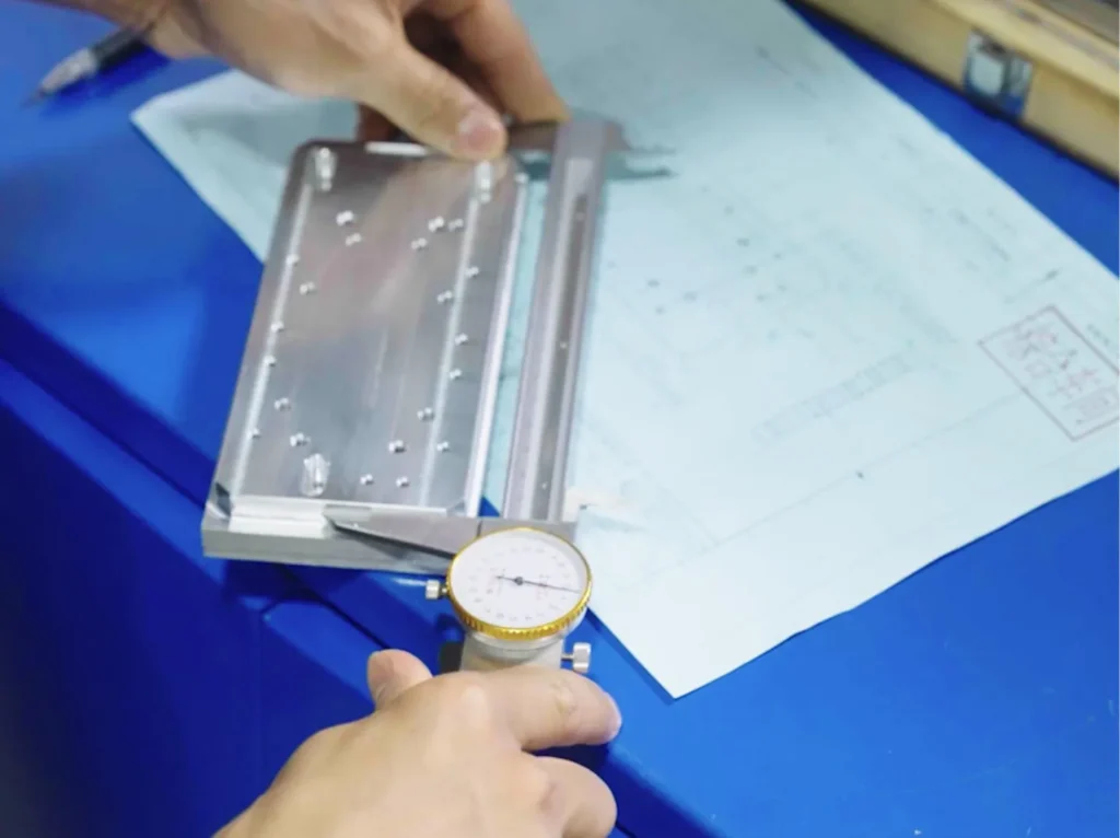
For the first-piece inspection, after the tool change operation of each batch and the first part processed after the program change, all dimensions and all geometric tolerances must be measured, including the passage and stop conditions of the thread gauge, as well as the surface roughness comparison block. And records must be archived and retained for at least 5 years.
In the process of stable production, one out of every thirty products must be selected for inspection. The detection tools used are pneumatic measuring instruments or laser displacement sensors to quickly detect key characteristics, such as hole diameter and shaft diameter. Once a trend deviation is detected, that is, three consecutive products exceed 75% of the control line, the machine must be stopped immediately to implement adjustment measures.
In the shipment batch verification process, a three-dimensional coordinate measuring machine must be used to conduct random inspections in accordance with the AQL (acceptable quality level) II standard. A zero-tolerance attitude must be adopted for major defects, such as when the size exceeds the tolerance range by more than 0.02mm.
Each part must be given an independent laser dot or pin-engraved serial number, and all measurement data must be analyzed through Q-DAS or similar statistical software. The closed-loop quality traceability system can bind the raw material heat number, processing program version, tool ID, operator, and inspection results of each milling and turning part. Once a failure occurs after-sales, the flow direction of 20 parts of the same batch can be locked within 2 hours.
07Repeat core ideas and action suggestions
Reconfirm the core point of view: using CNC automotive milling and turning parts can obtain ±0.005mm accuracy and complex geometric features at a controllable cost. The selection of materials should be based on the adaptability of machinability and service conditions, and the processing cycle of each piece and closed-loop quality traceability are two key factors for cost reduction and risk control. As for those companies that plan to purchase or establish their own CNC automotive parts processing capabilities, the following four actions are suggested that can be implemented immediately:
1. The reference standard is: obtain copies of the ISO 9001:2015 or IATF 16949 certification of at least three factories specializing in processing and production to check the length of time they have experienced in mass production of automobile parts.
2. To conduct trial cutting for verification, a three-dimensional model of a typical part must be provided, as well as 2D drawings, and the drawings must be marked with key tolerances. On this basis, the supplier is required to provide a CPk report and the three-dimensional coordinate data of the first piece during the trial production of 100 parts.
3. Calculate the cycle time: Based on your part design, please provide a simulated cycle time table covering the loading and unloading time, and clearly indicate the tool and fixture investment amortization method.
4. Action to embed traceability clauses in contracts: Add quality data link requirements to the purchase agreement. Each delivered part must be accompanied by a QR code. Scanning this QR code will display the part’s processing program ID, inspector information, and measured key dimensions.
Through the above-mentioned systematic technical assessment that requires strict compliance with certain process steps and risk management and control that requires comprehensive and careful consideration of various factors, you can ensure that the CNC automotive milling and turning parts you obtain can meet the life standard requirements stipulated in the design, and on the other hand, you can also achieve the goal of optimizing the total life cycle cost. If it is necessary to carry out feasibility analysis based on specific part drawings, then the materials, annual demand, key tolerances and surface treatment requirements must be compiled and summarized, and then we will provide targeted technical solutions.