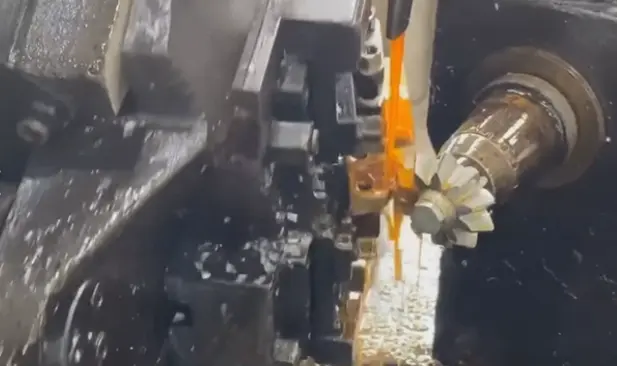
When it comes to copper castings precision CNC turning , manufacturers and engineers seek reliable methods to achieve tight tolerances, smooth surface finishes, and consistent part quality. This guide covers the essential practices for successful CNC turning of copper castings, supported by real-world examples and actionable recommendations. For high‑reliability results, YPMFG provides professional solutions tailored to copper casting machining needs.
01 Why Copper Castings Require Specialized CNC Turning
Copper and its alloys (such as C11000 electrolytic copper, C95400 aluminum bronze, or C83600 leaded red brass) are widely used in electrical connectors, valve bodies, heat exchangers, and hydraulic components. However, copper castings present unique challenges:
High ductility and adhesion – Copper tends to stick to cutting tools, causing built‑up edge.
Excellent thermal conductivity – Heat dissipates quickly, but that also means localized hardening at the shear zone.
As‑cast surface variations – Castings often have sand inclusions, porosity, or hard spots that affect tool life.
In one typical case, a valve manufacturer experienced frequent tool breakage when turning C83600 castings. By adopting the correct insert geometry and cutting parameters, they reduced tool wear by 60% and achieved a consistent 32 µin Ra surface finish.
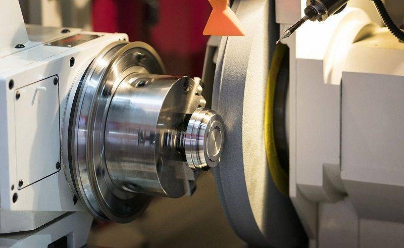
02 Key Parameters for Precision CNC Turning of Copper Castings
To achieve ISO 2768‑mK or tighter tolerances (eg, ±0.005”), follow these established practices:
Tool Selection
Insert material – Uncoated carbide or PCD (polycrystalline diamond) for high‑copper alloys. Coated carbides (eg, TiAlN) may cause built‑up edge.
Rake angle – Positive, sharp edge (10°–15° positive) to reduce cutting force and minimize adhesion.
Nose radius – 0.2–0.4 mm for finishing; 0.8 mm for roughing to distribute heat.
Cutting Conditions (Example for C11000)
For aluminum bronze (C95400), reduce speed by 20–30% due to higher strength.
Coolant and Chip Control
Use high‑pressure coolant (500–1000 PSI) directly at the cutting edge to flush chips and prevent re‑cutting.
Avoid chlorine‑based lubricants that may stress‑corrode copper alloys. Use semi‑synthetic or vegetable‑based fluids.
03 Common Problems and Proven Solutions
A real‑world example: an electrical terminal producer found that 15% of their C11000 turned parts had micro‑burrs causing assembly issues. They introduced a constant‑surface‑speed (G96) finishing pass at 800 SFM with a 0.002 IPR feed, eliminating burrs without an extra deburring step.
04 Quality Assurance for Copper Castings CNC Turning
To ensure every part meets specifications, implement these checks:
1. In‑process gauging – Use a contact or laser micrometer every 10–20 parts to catch thermal drift.
2. Surface finish measurement – A portable profilometer (Ra / Rz) per ISO 4287.
3. Dimensional inspection – CMM or dedicated hard gauges for critical features (eg, bore diameters, thread starts).
4. Material verification – Eddy current or conductivity testing to confirm alloy grade, especially for castings with unknown history.
05 Actionable Recommendations to Maximize Success
1. Always obtain a representative sample – Run a trial on 5–10 casting blanks before full production to validate toolpaths and workholding.
2. Partner with a specialist – Copper casting machining requires deep process knowledge. YPMFG has dedicated CNC turning centers with coolant‑through tooling and in‑house CMM inspection, ensuring every batch meets your dimensional and finish requirements.
3. Document your parameters – Record speed, feed, DOC, and tool life for each copper alloy. This builds a process library that reduces setup time by up to 40%.
06 Conclusion
Precision CNC turning of copper castings is fully achievable with correct tool selection, optimized cutting data, and rigorous quality checks. Prioritize sharp positive‑rake inserts, high‑pressure coolant, and finishing passes at elevated speeds to overcome common issues like built‑up edge and burrs. For manufacturers seeking consistent, high‑accuracy results without trial‑and‑error, YPMFG offers turnkey solutions from casting to finished machined parts. Choose YPMFG for your next copper casting project and experience reliable precision, on-time delivery, and expert support.


